Fortinet MR1 manual Front-Panel Components

Models: MR1

1 640
Download 640 pages 32.63 Kb
Page 25
Image 25

1.3 Front-Panel Components

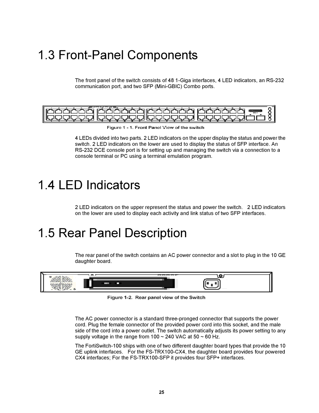
The front panel of the switch consists of 48 1-Giga interfaces, 4 LED indicators, an RS-232 communication port, and two SFP (Mini-GBIC) Combo ports.

4 LEDs divided into two parts. 2 LED indicators on the upper display the status and power the switch. 2 LED indicators on the lower are used to display the status of SFP interface. An RS-232 DCE console port is for setting up and managing the switch via a connection to a console terminal or PC using a terminal emulation program.

1.4 LED Indicators

2 LED indicators on the upper represent the status and power the switch. 2 LED indicators on the lower are used to display each activity and link status of two SFP interfaces.

1.5 Rear Panel Description

The rear panel of the switch contains an AC power connector and a slot to plug in the 10 GE daughter board.

The AC power connector is a standard three-pronged connector that supports the power cord. Plug the female connector of the provided power cord into this socket, and the male side of the cord into a power outlet. The switch automatically adjusts its power setting to any supply voltage in the range from 100 ~ 240 VAC at 50 ~ 60 Hz.

The FortiSwitch-100 ships with one of two different daughter board types that provide the 10 GE uplink interfaces. For the FS-TRX100-CX4, the daughter board provides four powered CX4 interfaces; For the FS-TRX100-SFP it provides four SFP+ interfaces.

25

Page 25
Image 25
Fortinet MR1 manual Front-Panel Components