SJ700-2 Series
Page
Safety Instructions
Installation
Wiring
! Warning
Operation
Maintenance, inspection, and parts replacement
Precautions Concerning Electromagnetic Compatibility EMC
Model No Required torque N-m Wire range AWG
Or 1/0
13.7
Model No Fuse/circuit breaker a Type Rating
30 a
40 a
60 a
Contents
Contents
Running time over and power-on time over signals RNT and ONT
Contents
Error Codes
Xii
Index
Xiii
Overview
Page
Specification label
Inspection of the Purchased Product
Inspecting the product
Method of Inquiry and Product Warranty
Product warranty
Warranty Terms
Method of inquiry
Exterior Views and Names of Parts
Installation and Wiring
Page
Installation and Wiring
Precautions for installation
Inverter
Ventilation fan
Inverter AcceptableUnacceptable
Inverter capacity kW 18.5 Loss with 70% load W
Loss with 100% load W
Joint Section to be cut off
Backing plate Rubber bushing
Wiring
Phase power supply
Hitachi
Explanation of main circuit terminals
Explanation of control circuit terminals
AL0
SW1
OFF on
Wiring of the main circuit
Inverter Grounding bolt prepared by user
Terminal layout Inverter model
Terminal layout
Charge lump
Terminal layout Inverter model Charge lump
Applicable peripheral equipment
100
Inverter Motor
200 to 240 V +10%, -15%
50/60 Hz ±5% 282 to 339 VDC
380 to 480 V +10%, -15%
50/60 Hz ±5%
TH FW 8 CM1
PL CM1 7 6
FW 8 CM1 14 13 11 AL1
CM1 15 CM2 12 AL0 AL2
When using the internal interface power supply
When using an external power supply
Sink logic
Source logic
BRD
Operation
Page
Operating Methods
! Warning
Frequency-setting command
Input device control Device switch
Control circuit terminal block
How To Operate the Digital Operator OPE-S
Monitor Power lamp Digit LED display
Names and functions of components
Code display system and key operations
Operation
Corresponding to the function code. Data display *1*2
Parameter type
STR key after changing the data
Pressing the STR key
Display the monitor mode code. d001 is displayed
How To Make a Test Run
ELB
Key to start the motor RUN lamp green LED goes on Press
Key to decelerate or stop the motor
CM1 PLC
Explanation of Functions
This chapter describes the functions of the inverter
Page
Monitor Mode
Output frequency monitoring
Output current monitoring
Rotation direction monitoring
Intelligent input terminal status
Intelligent output terminal status
Scaled output frequency monitoring
Torque command monitoring
Power monitoring
Actual-frequency monitoring
Torque bias monitoring
Cumulative power monitoring
Cumulative power-on time monitoring
Heat sink temperature monitoring
Motor temperature monitoring
Current position monitor in absolute position control mode
Life-check monitoring
Program counter display easy sequence function
Program number monitoring easy sequence function
Programming error monitoring
Trip monitoring 1 to
DC voltage monitoring
BRD load factor monitoring
Function Mode
Output frequency setting
Keypad Run key routing
Rotational direction restriction
Frequency source setting
Run command source setting
No contact
Active state C011 to C018 NC contact
Stop mode selection
Stop key enable
Acceleration/deceleration time setting
Deceleration time tB
Base frequency setting
Maximum frequency setting
External analog input setting O, OI, and O2
Frequency operation function
+fO2 + fO2
Start/end frequency setting for external analog input
Frequency addition function
External analog input O/OI/O2 filter setting
16 V/f gain setting
Start/end frequency settings for the O2-L terminal
17 V/F characteristic curve selection
VPf
Free-setting V/f frequency
To 400.Hz Free-setting V/f frequency
To free-setting V/f frequency 7 Hz
To free-setting V/f frequency 6 Hz
Torque boost setting
B083
DC braking DB setting
Edge mode A056
Example 1-a Example 1-b
Example 2-a Example 2-b
Example 3-a Example 3-b
Ii Example 5-a when the stop command is input
Ii Example 6-a when the stop command is input
Edge mode
Example 7-a
Example 7-b
Frequency upper limit setting
When the O-L or OI-L terminal is used
When the O2-L terminal is used
Acceleration stop frequency setting
Setting of 0 Hz disables the jump frequency function
Setting of the length of time to stop
Frequency setting Acceleration
PID function
OI-L + O2
OI + O2
Operation targets include + O2 Input to the OI terminal
Operation targets are the inputs To the OI and O terminals
01 %
FW on OFF FBV Onoff
Two-stage acceleration/deceleration function 2CH
Acceleration/deceleration curve selection
You can set different patterns of motor acceleration
Inverter
Use functions A097 and A098 to select acceleration
Energy saving mode tuning A086
Energy-saver operation
Accuracy
Retry or trip after instantaneous power failure
Power supply Inverter output Motor speed
Example 5 b00400
Example 6 b00401
Example 7 b00402
Example 8 b00400
Phase loss power input protection
Function code Data Description Phase loss detection
Enable Enabling the protection
Disabling the protection
Constant-torque characteristic
Characteristic
Free setting of electronic thermal characteristic
Electronic thermal protection
Setting of the current at each breakpoint
Setting of the threshold level to output
Thermal warning signal
Disabling the electronic thermal protection
Overload restriction/overload notice
Overcurrent restraint
Over voltage supression during deceleration
Start frequency setting
Reduced voltage start function
Carrier frequency setting
Class
Automatic carrier frequency reduction
Function code Range of data Description Automatic carrier
00/01 Invalid, 01 valid Frequency reduction
Cooling-fan operation setting
Dynamic braking BRD function
Intelligent input terminal setting
Input terminal a/b NO/NC selection
Bit operation mode
By setting multispeeds 1 to 7 A021 to A027
Make multispeed s 0 to 7 available for selection
If two or more input terminals are turned on at the same
Jogging JG command setting
Jog stop mode
43 2nd/3rd motor control function SET and SET3
Software lock SFT function
Forcible-operation from terminal F-TM function
Free-run stop FRS function
Commercial power source switching CS function
Reset RS function
Example 4 Restarting with active matching frequency
Remote control function UP and DWN
Unattended start protection USP function
53 3-wire interface operation function STA, STP, and F/R
External trip EXT function
Control gain switching function CAS
55 P/PI switching function PPI
Analog command holding function AHD
Speed error at rated torque a
Intelligent pulse counter Pcnt and PCC
Synchronous rotation speed at base frequency
Intelligent output terminal setting
Example of operation as an alarm output terminal
Intelligent output terminal a/b NO/NC selection
Disabling the output of frequency
C042/C045 043/C046
63 0 Hz speed detection signal ZS
Over-torque signal OTQ
Alarm code output function AC0 to AC3
Logical output signal operation function LOG1 to LOG6
Capacitor life warning signal WAC
Communication line disconnection signal NDc
Cooling-fan speed drop signal WAF
Starting contact signal FR
Heat sink overheat warning signal OHF
Low-current indication LOC signal
Forward rotation signal FWR
Irdy Inverter ready signal
FWR Forward rotation signal
Reverse rotation signal RVR
Major failure signal MJA
RVR Reverse rotation signal
MJA Major failure signal
WCO/WCOI/WCO2
Output signal delay/hold function
Input terminal response time
External thermistor function TH
FM terminal
Pulse output terminal
FM siginal selection
Function code Range of data Description
AM and AMI terminals
Initialization setting
Function code display restriction
Explanation of Functions
Last equivalent to the setting on SJ300
Automatic user-parameter setting
Stabilization constant setting
Selection of operation at option board error
Page
Brake control function
Signal has been output until the brake is
Brake Wait Time for Mechanical delay after the release
Wait time longer than the delay after
Release signal output until the release
B054 B053
B052
Offline auto-tuning function
When using this function, follow the instructions below
Normal end Abnormal end
Online auto-tuning function
Automatically tuned data online auto-tuning enabled
Function code Data Description Temperature compensation
Disabling the secondary resistance compensation
Then adjust the speed response H005/H205
Motor constants selection
Io as follows
Voltage class 200 or 400
Sensorless vector control
Sensorless vector, 0 Hz domain control
Zero LV lmit
Current limiter for the low-speed range
Zero LV starting boost current
Torque monitoring function
Forcing function FOC
Output torque
Motor capacity selection
Torque limitation function
Enable Enabling counterrotation prevention
Reverse Run protection function
B041 B042 B044 B043
Disabling counterrotation prevention
Torque LAD stop function
High-torque multi-motor operation
Easy sequence function
Personal computer Windows system
2 V2 control pulse setting
Functions requiring the SJ-FB
Vector control with encoder feedback
Torque-limited operation at
Operation Torque limiter level
Torque biasing function
Torque control function
Pulse train position control mode
Control block diagram
Frequency command Hz =
255
MD1 Forward/reverse operation command with pulse train
SBP SBP
Electronic gear function
P019 = 00 FB
P019 = 01 REF
Example of use Synchronous operation
Master inverter Slave inverter
Main motor Sub-motor
Motor gear ratio setting function
Setting of the actual pulse
Count of encoder
Home search function
10243072 2048
Absolute position control mode
Operation in absolute position control mode
Operation Output frequency Speed setting POK signal
Multistage position switching function CP1/CP2/CP3
Speed/position switching function SPD
Forward direction at the low-speed
Position range specification function
Forward/reverse drive stop function FOT/ROT
Teaching function
Teaching selection P074
Servo-on function
SON Fwrv
Block diagram for pulse train frequency input
Setting of the filter time constant for
Pulse train frequency input
To +100. % Pulse train frequency limit
Communication specifications
Communication Functions
Set this item when your inverter is
Communication mode
Ascii mode
Selection Modbus-RTU mode
Explanation of Functions
Communication in Ascii mode
STX 0101000500 BCC CR 0230 3130 3130 30 30 35 30 3030 350D
Data to be transmitted
Explanation of Functions
Response frame Frame format
Data
Inverter status a Inverter status B Inverter status C
Data Bytes See Note
Status a Status B Status C Reserved
Data monitored at tripping
Inverter status B Bytes
Inverter status C Bytes
Bytes Decimal Ascii code Output current
Station No. Command Parameter
Response frame Positive response Frame format
Data parameter number Bytes See Note
Station No
Station No. Command Parameter Data
Station No. Command
Parameter data decimal Ascii Bytes See Note Code
Data Bytes Enabling data storage
Explanation of Functions
Ii Negative response Response frame Frame format
Transmission frame configuration Station No. Command
Reference Ascii code conversion table
This result is used as BCC
Character data Ascii code
Communication in Modbus-RTU mode
Function code Maximum number of data
Reads the coil status
Reads registers
Writes data to a coil
CRC*1
Slave address Function code Exception code CRC-16
Code Description
An unsupported function is specified
Specified address is not found
Intelligent input terminal Coil number
Terminal status
Read the data received in the response as follows
Field name Sample setting
Coil status
Updating data upper digit FFh
Updating data lower digit
Query Response Field name Sample setting
Intelligent input terminal
Slave address Function code Exception code CRC-16 code
Exception codes
01h An unsupported function is specified
02h Specified address is not found
Data to be written Description
Recalculating the motor constants
Storing the register data
Coil No Setting
LOG2 logical operation result ON, 0 OFF
Ii List of registers frequency settings and trip monitoring
Register Function name Monitoring and setting items Data
Option 1 error 0 to
Option 2 error 0 to
List of inverter trip factors
Iii List of registers monitoring
Iv List of registers
List of registers function modes
Start frequency to
Monitoring and setting items Data resolution
12B4h
Failure time
Monitoring and setting items Data resolution Register
During inverter operation including 5 minutes after
EXT external trip, 13 USP unattended start
Thermal overload, 07 LAD frequency, 09 motor
C042 high
1487h Output 11 off-delay time C131
1506h
Over-speed error detection level P026 Setting
To the allowable maximum frequency
Code data
Vi List of registers 2nd control settings
2506h Motor
Viii List of registers 3rd control settings
Ix List of registers 3rd control setting
Error Codes
Error Codes and Troubleshooting ···················· 5
Page
Error Codes and Troubleshooting
Error Codes
CPU
GA.COM
Adjust
Option boards error codes
Input mode specified by switch settings
Setting of MAC ID DIP switches No to No
Baud rate Kbps DIP switch setting
= 29 hexadecimal = 41 decimal
Error code is output when the relevant program runs
Trip conditions monitoring
305 A004/A204/A304 A202/A220/A320 *2 006
Precautions for Maintenance
Ground Resistance Test with a Megger
Method of Checking the Inverter
DC-Bus Capacitor Life Curve
Page
Precautions for Maintenance and Inspection
Cleaning
Daily inspection
Periodic inspection
Daily and Periodic Inspections
Ground terminals with a megger
Ground Resistance Test with a Megger
Withstand Voltage Test
Method of Checking the Inverter and Converter Circuits
DC-Bus Capacitor Life Curve
Output of Life Warning
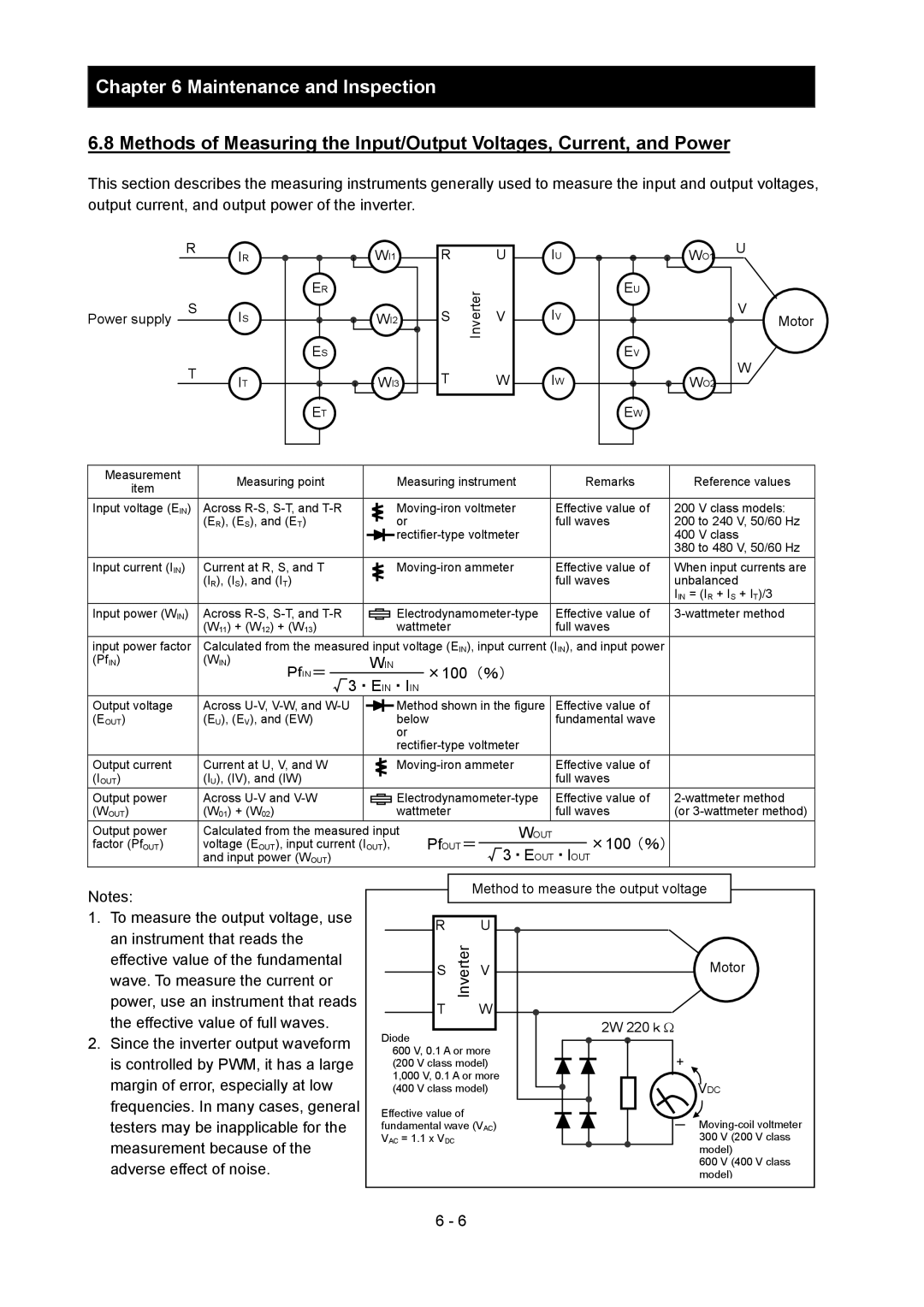
PfIN=
Method to measure the output voltage
Motor 2W 220kΩ
Specifications
Specifications External dimensions
Page
Specifications
Specifications of the 200 V class model
Specifications of the 400 V class model
Common specifications of 200 V class and 400 V class models
Standard
Model name type 055 075 110 150 185 220 300 370 450 550 Name
External dimensions
SJ700-055 to110LFF2/LFUF2 / HFF2/HFEF2/HFUF2
SJ700-150 to 220 LFF2/LFUF2 / HFF2/HFEF2/HFUF2
SJ700-300 LFF2/LFUF2 / HFF2/HFEF2/HFUF2
SJ700-550 LFF2/LFUF2
List of Data Settings
Monitoring Mode Function Mode Extended Function Mode
Page
Precautions for Data Setting
Function Mode
Extended Function Mode
PID
AVR
B004 Failure/under-voltage trip alarm To stop Enable
Power
Free-setting V/f voltage To 800.0
Input
Analog
C107 AMI gain adjustment To 200. %
Setting C163 Input terminal response time To 200. ¯2ms
Control
Control
RPM
Specification
List of Data Settings
Allowed or Not No/d001 to P131
Appendix
Upgrading from the SJ300 Series
Copying the parameter settings
Index
High-resolution absolute position Control 106
Instantaneous power failure
Instantaneous power failure or
Monitor mode Motor constant
Operation time over signal RNT/plug-in time over signal
Phase loss input Phase loss input protection
Remote operator Appendix-1 Reset
Running time over / power-on time Over
Gain setting VP 1.7 th power
Window comparator Wiring of control circuit terminal
Thermistor
Torque biasing