Duplex Models
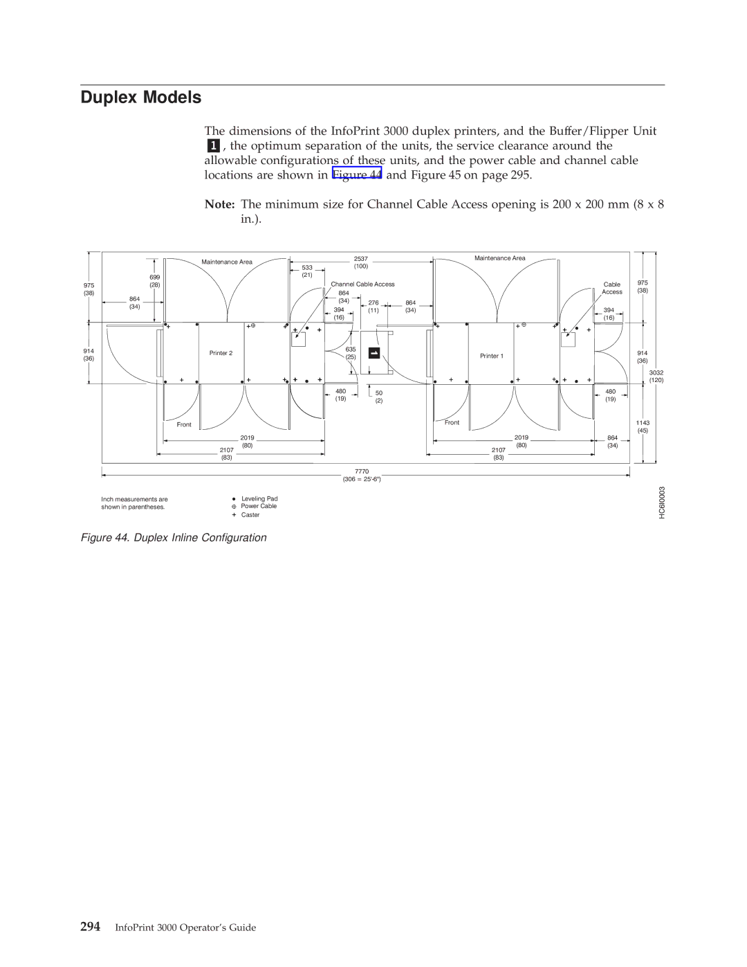
The dimensions of the InfoPrint 3000 duplex printers, and the Buffer/Flipper Unit „1…, the optimum separation of the units, the service clearance around the allowable con®gurations of these units, and the power cable and channel cable locations are shown in Figure 44 and Figure 45 on page 295.
Note: The minimum size for Channel Cable Access opening is 200 x 200 mm (8 x 8 in.).
|
| Maintenance Area | 2537 |
|
|
|
| (100) |
| ||
|
| 533 |
| ||
| 699 | (21) |
|
|
|
|
|
|
|
| |
975 | (28) |
| Channel Cable Access |
| |
(38) | 864 |
| 864 |
|
|
|
| (34) | 276 | 864 | |
| (34) |
| |||
|
|
| |||
|
| 394 | (11) | (34) | |
|
|
| |||
|
|
| (16) |
|
|
914 |
| Printer 2 | 635 |
|
|
| (25) |
|
| ||
(36) |
|
|
| ||
|
|
|
| ||
|
|
|
|
| |
|
|
| 480 | 50 |
|
|
|
| (19) |
| |
|
|
| (2) |
| |
|
|
|
|
| |
Front
2019
(80)
2107
(83)
7770
(306 =
Maintenance Area
Cable 975
Access (38)
394
(16)
Printer 1 | 914 | |
(36) | ||
|
3032
(120)
| 480 |
| (19) |
Front | 1143 |
| (45) |
2019 | 864 |
(80) | (34) |
2107 |
|
(83) |
|
Inch measurements are | Leveling Pad |
shown in parentheses. | Power Cable |
| Caster |
HC6I0003
