IBM
Page
IBM
Second Edition October
Online Documentation Authorization
Iv InfoPrint 3000 Operators Guide
Contents
Ordering and Replacing
Glossary 297
Viii InfoPrint 3000 Operators Guide
Figures
InfoPrint 3000 Operators Guide
Tables
Xii InfoPrint 3000 Operators Guide
IBM Warranty
Statement of Limited Warranty
Production Status
Extent of Warranty
Warranty Service
Limitation of Liability
Xvi InfoPrint 3000 Operators Guide
Xvii
Communication Statements
Trademarks
Japanese Vcci
Taiwan EMC
Safety Notice Conventions
Page
Safety Notices
Laser radiation when open Avoid exposure to beam
Environmental Information
New Operators
How to Use This Book
Preface
About This Book
All Operators
Terminology
Notation Conventions
Pictorial Conventions
Related Publications
InfoPrint 3000 Library
Xxviii InfoPrint 3000 Operators Guide
Summary of Changes
Xxx InfoPrint 3000 Operators Guide
Introduction
System Characteristics
Chapter Overview
Lbs Max. mm Min. mm
DPI IPM
System Components
Printer Characteristics
Duplex Printing Applications
Simplex and Dual Simplex Printing Applications
Inline Conguration for Duplex
Left Angle Conguration for Duplex
Left Angle Conguration for Dual Simplex
Operators Overview
What to Do When to Do It Where to Find More Information
Operator Responsibilities
Operator Responsibilities
Normal Operation Ready Status
Operator Intervention Not Ready Status
Service Call Procedure
InfoPrint 3000 Operators Guide
Forms and the Forms Path
Functional Areas
Keep In Mind
Used for simplex printing and is using boxed fan-fold forms
Control Unit Area
For Customers
Power Control Panel
Operator Alert Area
Display Touch Screen
Functional Areas
Developer Area
Developer Area Controls
Forms Input and Transfer Station Area
Printer Control Panel
Using This Control Does This
Control Lever
Transfer Station Control Lever and Tractor Control Levers
Fuser Entry Area
Puller Control Lever
Stacker Area
Table Forms Feed
Stacker Control Panel
Forms Select
Forms Feed
Forms Length
Forms Length and Width Controls
Stacker Height Control
Stacker Height Control
Rear Service Area
Using the Display Touch Screen
Main Window
Display Touch Screen Windows
Keyboard, Keypad, and Hexpad Windows
Left
Delete
Home
End
Selectable Field
Selection Devices on the Display Touch Screen Windows
Fingertip Control
Pushbuttons
Scroll Bar
Radio Buttons
Inactive Items
Print Screen
Control Procedures System Menu
Multiple Procedures
Switch to
Switch To
Screen Saver Timeout
Visual Cue
Symbols and Visual Cues
Explanation
A26O0020
Task Summary
Authorization level that is required of each procedure
Npro
Operate Pull-Down Menu
Shutdown/Restart
Npro
Congure Pull-Down Menu
InfoPrint 3000 Operators Guide
Print Samples
Service Actions
Analyze Pull-Down Menu
Traces
Options Pull-Down Menu
Calibrate Touch Screen
Special Features
Front Face
General Help Window
Help Pull-Down Menu
Dene Forms Help Window
Additional Help
InfoPrint 3000 Operators Guide
Operator Responsibilities
Controlling the System Power
Powering On the System
Local/Remote Power Control
Element Remote Power Controlled From
Host-Controlled Remote Mode
Local-Controlled Mode
Emergency Power Off
Powering Off the System
Shutting Down the System
Shutting Down and Restarting the System
From the Operate pull-down menu, Select Shutdown/Restart
Restarting the System
Local Channel Enable/Disable
Remote Channel Enable/Disable
Enabling and Disabling Attachments
Enabling a Host Attachment
User Controls
Adjusting the Display Touch Screen Monitor
Row Submenu Function
On-Screen-Display Controls
Cancel
Requirement For This Procedure
Adjusting the Print Position
Kuhlly Conditioning
Select the Number of Pages box
Select the Side to Adjust eld
How This Procedure Works
Things To Keep In Mind When You Adjust the Print Position
What If the Adjustment Required Is Out of Range
Operator Tips
Sample Field Adjusted Registration
Operator Tips
Adjusting the Volume of the Operator Alert Assembly
Npro Procedure
Advancing Forms Using the Npro and Npro Page Functions
Requirements For Npro To Function
Npro Page Procedure
Simplex Mode
Canceling a Job
Initial Operation
Changing the Password or Authorization Level
Options Pull-Down Menu
Checking for a Front-Facing
This procedure assumes the following
Operator Responsibilities
Checking the Forms Alignment
Checking Print Quality
Cleaning the Oiler Belt
HC6OG051
Recommendations for Cleaning the Printer
Cleaning the Printer
Operator Responsibilities
Developer Area
Important Note About the Coronas
Forms Input Area
Transfer Station Area
Raise the transfer station
HC6OG095
Important Note About Cleaning the Coronas
Stacker Area
InfoPrint 3000 Operators Guide
Fuser Area
Important Note About Cleaners
Connecting an Accessory to the Operator Alert Contacts
Loading Forms Simplex or Dual Simplex Mode
Operator Responsibilities
AT the Stacker
Operator Responsibilities
InfoPrint 3000 Operators Guide
Operator Responsibilities
InfoPrint 3000 Operators Guide
Operator Responsibilities
InfoPrint 3000 Operators Guide
Operator Responsibilities
AT the Transfer Station
Operator Responsibilities
AT the Display Touch Screen
Loading Forms Duplex Mode
Do on page 103 through on page 110 under ªLoading Forms
Adjusting the Stacker Table Height
Port Conguration Options
Powering On and Off Pre/Post Devices
Preprocessing and Postprocessing Instructions
Enabling/Disabling Pre/Post Interfaces
Error and Jam Recovery
Using the Printer Stacker
Adding Supplies
Nonprocess Runout Npro
Reprint Path Length
Recovering from a Forms Jam Simplex Operations
Jams Within the Printer Engine
Error Message SRC Code In Numeric Order Recovery Actions
Jam Recovery Procedures
Forms are jammed, torn, or separated
Separated
Forms are not jammed, torn, or
Stacker mechanism
These errors are not set when a
Postprocessing Device Interface feature
Is installed and enabled, which disables
Jams Between the Printer and a Postprocessing Device
Duplex Mode Reprint Path Length
Recovering from a Forms Jam Duplex Operations
InfoPrint 3000 Operators Guide
Jams Within Printer
Error Message SRC Code In Numeric Recovery Actions Order
Reestablishing Forms Alignment
Check Reset pushbutton on the Display Touch Screen window
0132
Mechanism
Postprocessing device is installed
Enabled, which disables the stacker
Ensure correct forms folding when printing resumes
Jam Between Printer 1 and Printer
Recovering from a Forms Jam in the Postprocessing Device
Clearing the Forms Path Transfer Station Area
Operator Responsibilities
InfoPrint 3000 Operators Guide
Operator Responsibilities
Fuser and Stacker Areas
Operator Responsibilities
CAUT0100
Stacker and Pendulum Area
Suggestions for Preventing Jams
Operator Responsibilities
Reporting Printer Usage
Printer Usage Sheet
Select the Start Trace pushbutton
Running Traces
Select the Stop Trace pushbutton
Select the How Many? eld
Select the Dene Form procedure
Adjusting the Preheat Temperature
Forms Stick Together
Poor Fusing Simplex Mode
Heat Damage Ð Printer Running
Thread/Align Forms
Setup Window for Thread/Align Forms
Forms are broken between the printers
Forms are not loaded in printer 2 Select this when
Main Thread/Align Forms Window
Forms Are Loaded Through Both Printers
Select the Forms are Connected pushbutton
Select the No option within the Print While Threading? eld
Select the Yes option within the Print While Threading? eld
Operate menu
This prints a dashed alignment mark after the leading edge
Forms Are Not Loaded In Printer
Printer 1, which is designated as an alignment
Print While Threading
This prints a dashed alignment mark after the leading edge
Forms Are Broken Between the Printers
Printer 1 Feed Page pushbutton
After you have completed the splicing procedure, go to step
Printing While Threading
InfoPrint 3000 Operators Guide
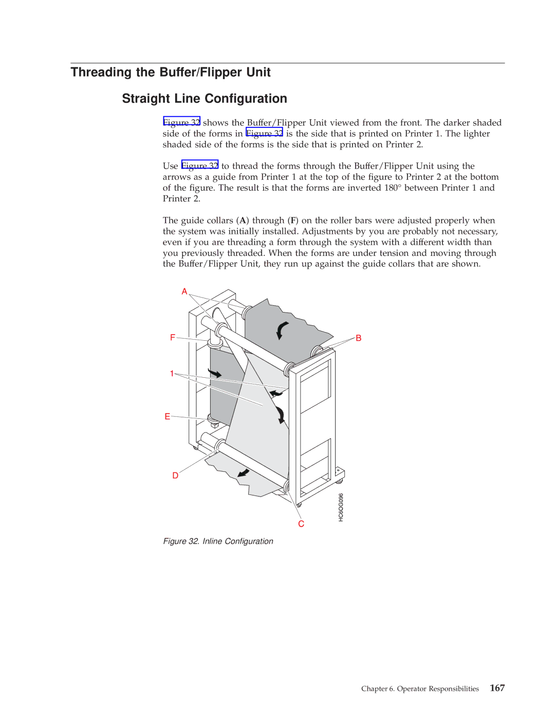
Inline Conguration
Threading the Buffer/Flipper Unit Straight Line Conguration
Left Angle Conguration
Left Angle Conguration
Forms Length
Unloading the Stacker
InfoPrint 3000 Operators Guide
Do not attempt to remove a full stack from the stacker
Operator Tips on Removing Forms From The Stacker
Select the Duplex item
Switching Printer Modes Dual Simplex/Duplex
Switching from Duplex to Dual Simplex Mode
Switching from Dual Simplex to Duplex Mode
Effect the Duplex main Display Touch Screen window appears
Switching Print Resolution
Ordering and Replacing Supplies
IBM Supplies Worksheet
Supplies
Important Notes Concerning Supplies
Ordering Supplies
Maintenance Supply Items
Customer-Replaceable Supply Items
Storing Supplies
Temperature
Relative Humidity
Adding Fuser Oil
Operator Tip
HC6OG070
Changing the Toner Cartridge
Ordering and Replacing Supplies
InfoPrint 3000 Operators Guide
Ordering and Replacing Supplies
Checking the Toner Collector
Ordering and Replacing Supplies
Changing the Toner Collector
Ordering and Replacing Supplies
InfoPrint 3000 Operators Guide
Changing the Developer Mix
InfoPrint 3000 Operators Guide
HC6OG036
InfoPrint 3000 Operators Guide
Ordering and Replacing Supplies
InfoPrint 3000 Operators Guide
Developer Drain Lever B downward and then pushing it
Operator Tip
Ordering and Replacing Supplies
Checking the Fine Filter
Changing the Fine Filter
InfoPrint 3000 Operators Guide
Ordering and Replacing Supplies
Changing the Oiler Belt
CAUT0100
HC6OG051
Ordering and Replacing Supplies
InfoPrint 3000 Operators Guide
Operator Tip
Against the spring
Ordering and Replacing Supplies
Checking the Absorbent Pad in the Oil Pan
Open the oiler-belt gate
InfoPrint 3000 Operators Guide
HC6OG073
InfoPrint 3000 Operators Guide
Conguring the System
Changing the Language of Messages
Congure Printer Window
Conguring the Printer
Select the Print pushbutton on the Print Conguration window
Printer Conguration Information
Conguration Item Description Value Options
Conguration Item Description Value Options
Conguration Item Description Value Options
Conguration Item Description Value Options
Conguration Item Description Value Options
Conguration Item Description Value Options
See information in Beam 1 offset adjustment
Conguration Item Description Value Options
Conguring the Host Attachments
Select the View... or Congure... pushbutton
Conguring the System
Parallel Channel Conguration Information
Conguration Item Description Value Options
Escon Channel Conguration Information
Token Ring TCP/IP Attachment Information
Conguration Item Description Value Options
Ethernet TCP/IP Attachment Information
Conguration Item Description Value Options
Fddi TCP/IP
Fddi TCP/IP Attachment Information
Conguration Item Description Value Options
Conguring Preprocessing/Postprocessing Devices/Interfaces
Select the New Processor... pushbutton
Congure Pre/Postprocessors Window Duplex Mode
Is grayed out in the Congure Pre/Postprocessors
Pre/Postprocessor Characteristics
Pre/Postprocessor Conguration Values
Selectable Field/Item Description Value Options
Selectable Field/Item Description Value Options
Select the Remote Access procedure
Conguring Remote Access
InfoPrint 3000 Operators Guide
Dening Forms
Select the New Form... pushbutton
Dene Forms Window Duplex Mode
Setting the Preheat Platen Temperature
Forms are then available for the Assign Forms to Load window
Selected Values Available Values Duplex Dual Simplex Printer
Duplex Conguration Worksheet
Selected Values Available Values Duplex Dual Simplex Printer
Escon Channel
Parallel Channel Attachment
Ethernet TCP/IP Conguration
Token Ring TCP/IP Conguration
Fddi TCP/IP Conguration
Device Number
Characteristics
Printer Number Port Number
Selected Values Available Values Duplex Dual Simplex Printer
Available Values Selected Value
Simplex Conguration Worksheet
Parallel Channel
Device Number
Port Number Enabled Yes / No
Device Number
Form Identication Worksheets
Form Identication Worksheet
Print Quality and Problem Solving
Symptom Action
Print Quality Problems
23±42lbs ±135kg 83±157g
Plastic
Sudden Failures
Symptom Discussion Suggested Action
Problem Solving Tips and Suggested Actions
Screen Printer Status
Lighter Contrast Control key on
Responding to Messages
Soft Program Check
Program Check Messages
± Select the Continue pushbutton
Hard Program Checks
Postpone
Printer Error Messages
Check Reset
Completed
Responding to Messages
Out of Supplies Window
Out Of Supplies Messages
Shows a sample Intervention Required window
Intervention Required Messages
System Status „3… This eld contains
Status Messages
Printer Status „2…
Attachments Status „1…
Messages
Status Message Summary
Message Description
Intervention Required
Printer Error
Messages with System Reference Codes
Out of Supplies
Code Message Text Type Printer Error unless
Code Message Text Type Printer Error unless
Code Message Text Type Printer Error unless
Code Message Text Type Printer Error unless
Code Message Text Type Printer Error unless
Code Message Text Type Printer Error unless
Code Message Text Type Printer Error unless
Code Message Text Type Printer Error unless
Code Message Text Type Printer Error unless
InfoPrint 3000 Operators Guide
Appendix A. Valid Form Lengths in Inches
InfoPrint 3000 Operators Guide
Simplex Models
Appendix B. Physical System Layouts
Duplex Inline Conguration
Duplex Models
Duplex Left Angle Conguration
InfoPrint 3000 Operators Guide
Afccu
Glossary
InfoPrint 3000 Operators Guide
Glossary
IBM branch office. The local IBM sales office
Glossary
OS/VS
Glossary
InfoPrint 3000 Operators Guide
Changing
Index
Developer
Forms Width
Snmp
Toner
InfoPrint 3000 Operators Guide
Please tell us how we can improve this book
How satised are you that the information in this book is
IBM
Page
IBM