www.ti.com
SRIO Registers
5.13SERDES Receive Channel Configuration Registers n (SERDES_CFGRXn_CNTL)
There are four of these registers, to support four ports.
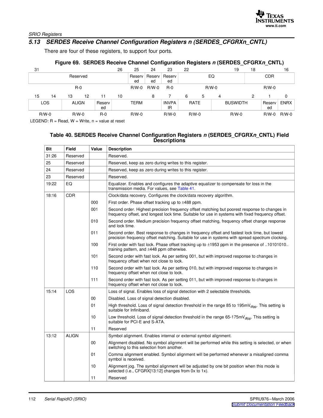
Figure 69. SERDES Receive Channel Configuration Registers n (SERDES_CFGRXn_CNTL)
31 |
|
|
|
| 26 | 25 | 24 | 23 | 22 |
|
| 19 | 18 |
| 16 |
|
| Reserved |
|
| Reserv | Reserv | Reserv |
|
| EQ |
|
| CDR |
| |
|
|
|
|
|
| ed | ed | ed |
|
|
|
|
|
|
|
|
|
|
|
|
|
|
|
|
| ||||||
15 | 14 | 13 | 12 | 11 | 10 |
| 8 | 7 | 6 | 5 | 4 |
| 2 | 1 | 0 |
| LOS | ALIGN | Reserv |
| TERM |
| INVPA |
| RATE |
| BUSWIDTH |
| Reserv | ENRX | |
|
|
|
| ed |
|
|
| IR |
|
|
|
|
| ed |
|
|
|
|
|
|
|
| |||||||||
LEGEND: R = Read, W = Write, n = value at reset
Table 40. SERDES Receive Channel Configuration Registers n (SERDES_CFGRXn_CNTL) Field
Descriptions
Bit | Field | Value | Description |
31:26 | Reserved |
| Reserved. |
25 | Reserved |
| Reserved, keep as zero during writes to this register. |
24 | Reserved |
| Reserved, keep as zero during writes to this register. |
23 | Reserved |
| Reserved. |
19:22 | EQ |
| Equalizer. Enables and configures the adaptive equalizer to compensate for loss in the |
|
|
| transmission media. For values, see Table 41. |
18:16 | CDR |
| Clock/data recovery. Configures the clock/data recovery algorithm. |
|
| 000 | First order. Phase offset tracking up to ±488 ppm. |
|
| 001 | Second order. Highest precision frequency offset matching but poorest response to changes in |
|
|
| frequency offset, and longest lock time. Suitable for use in systems with fixed frequency offset. |
|
| 010 | Second order. Medium precision frequency offset matching, frequency offset change response |
|
|
| and lock time. |
011Second order. Best response to changes in frequency offset and fastest lock time, but lowest precision frequency offset matching. Suitable for use in systems with spread spectrum clocking.
100First order with fast lock. Phase offset tracking up to ±1953 ppm in the presence of ..10101010.. training pattern, and ±448 ppm otherwise.
101Second order with fast lock. As per setting 001, but with improved response to changes in frequency offset when not close to lock.
| 110 | Second order with fast lock. As per setting 010, but with improved response to changes in |
|
| frequency offset when not close to lock. |
| 111 | Second order with fast lock. As per setting 011, but with improved response to changes in |
|
| frequency offset when not close to lock. |
15:14 | LOS | Loss of signal. Enables loss of signal detection with 2 selectable thresholds. |
| 00 | Disabled. Loss of signal detection disabled. |
| 01 | High threshold. Loss of signal detection threshold in the range 85 to 195mVdfpp. This setting is |
|
| suitable for Infiniband. |
| 10 | Low threshold. Loss of signal detection threshold in the range |
|
| suitable for |
| 11 | Reserved |
13:12 | ALIGN | Symbol alignment. Enables internal or external symbol alignment. |
00Alignment disabled. No symbol alignment will be performed while this setting is selected, or when switching to this selection from another.
01Comma alignment enabled. Symbol alignment will be performed whenever a misaligned comma symbol is received.
10Alignment jog. The symbol alignment will be adjusted by one bit position when this mode is selected (i.e., CFGRX[13:12] changes from 0x to 1x).
| 11 | Reserved |
112 | Serial RapidIO (SRIO) | SPRU976 |