www.ti.com
Interrupt Conditions
4Interrupt Conditions
This section defines the CPU interrupt capabilities and requirements of the peripheral.
4.1CPU Interrupts
The following interrupts are supported by the RIO peripheral.
∙Error Status: Event indicating that a
∙Critical Error: Event indicating that a critical error state was reached. The CPU should reset the system.
∙CPU servicing: Event indicating that the CPU should service the peripheral.
4.2General Description
The RIO peripheral is capable of generating various types of CPU interrupts. The interrupts serve two general purposes: error indication and servicing requests.
Since RapidIO is a packet oriented interface, the peripheral must recognize and respond to inbound signals from the serial interface. There are no GPIO or external pins used to indicate an interrupt request. Thus, the interrupt requests are signaled either by an external RapidIO device through the packet protocols discussed as follows, or are generated internally by the RIO peripheral.
CPU servicing interrupts lag behind the corresponding data, which was generally transferred from an external processing element into local L2 memory. This transfer can use a messaging or direct I/O protocol. When the single or
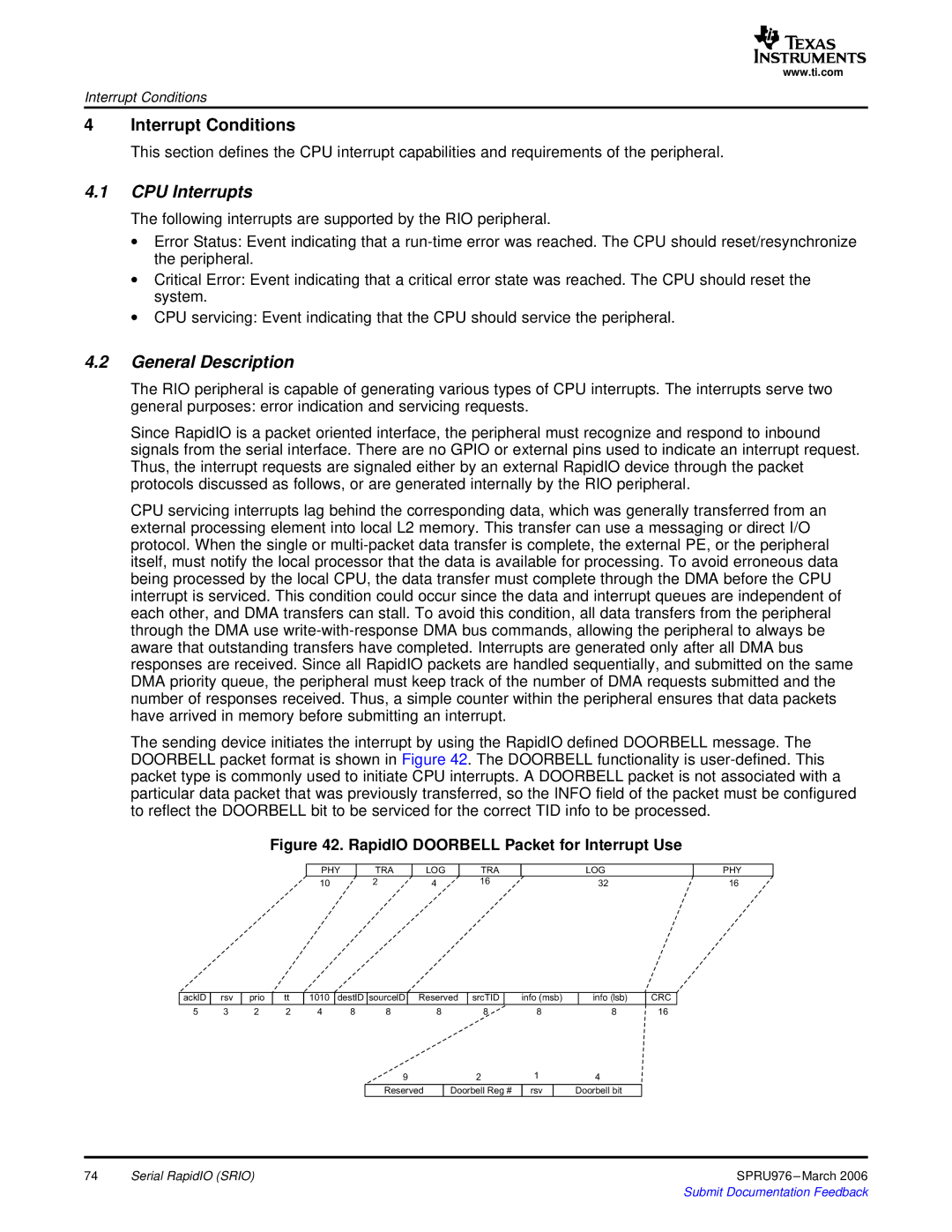
The sending device initiates the interrupt by using the RapidIO defined DOORBELL message. The DOORBELL packet format is shown in Figure 42. The DOORBELL functionality is
Figure 42. RapidIO DOORBELL Packet for Interrupt Use
PHY | TRA | LOG | TRA | LOG |
10 | 2 | 4 | 16 | 32 |
PHY
16
acklD | rsv | prio | tt | 1010 | destID | sourcelD | Reserved | srcTID | info |
| info |
| CRC | |||
5 | 3 | 2 | 2 | 4 | 8 | 8 |
| 8 |
| 8 | 8 | 8 | 16 | |||
|
|
|
|
|
| 9 |
|
| 2 | 1 | 4 |
|
| |||
|
|
|
|
|
|
|
|
|
|
|
|
|
|
|
|
|
|
|
|
|
|
| Reserved |
| Doorbell |
| rsv | Doorbell |
|
| |||
74 | Serial RapidIO (SRIO) | SPRU976 |