www.ti.com
Interrupt Conditions
∙Bit 21- Transaction was not sent due to DMA data transfer error, LSU3
∙Bit 22- Retry Doorbell response received or Atomic
∙Bit 23- Packet not sent due to unavailable outbound credit at given priority, LSU3
∙Bit 24- Transaction complete, No Errors
∙Bit 25-
∙Bit 26- Transaction was not sent due to Xoff condition, LSU4
∙Bit 27- Transaction was not sent due to unsupported transaction type or invalid field encoding LSU4
∙Bit 28- Transaction Timeout Occurred, LSU4
∙Bit 29- Transaction was not sent due to DMA data transfer error, LSU4
∙Bit 30- Retry Doorbell response received or Atomic
∙Bit 31- Packet not sent due to unavailable outbound credit at given priority, LSU4
Note: Enable for this interrupt is ultimately controlled by the Interrupt Req register bit of the Load/Store command registers. This allows enabling/disabling on a per request basis. For optimum LSU performance, interrupt pacing should not be used on the LSU interrupts. Section 4.6 describes interrupt pacing.
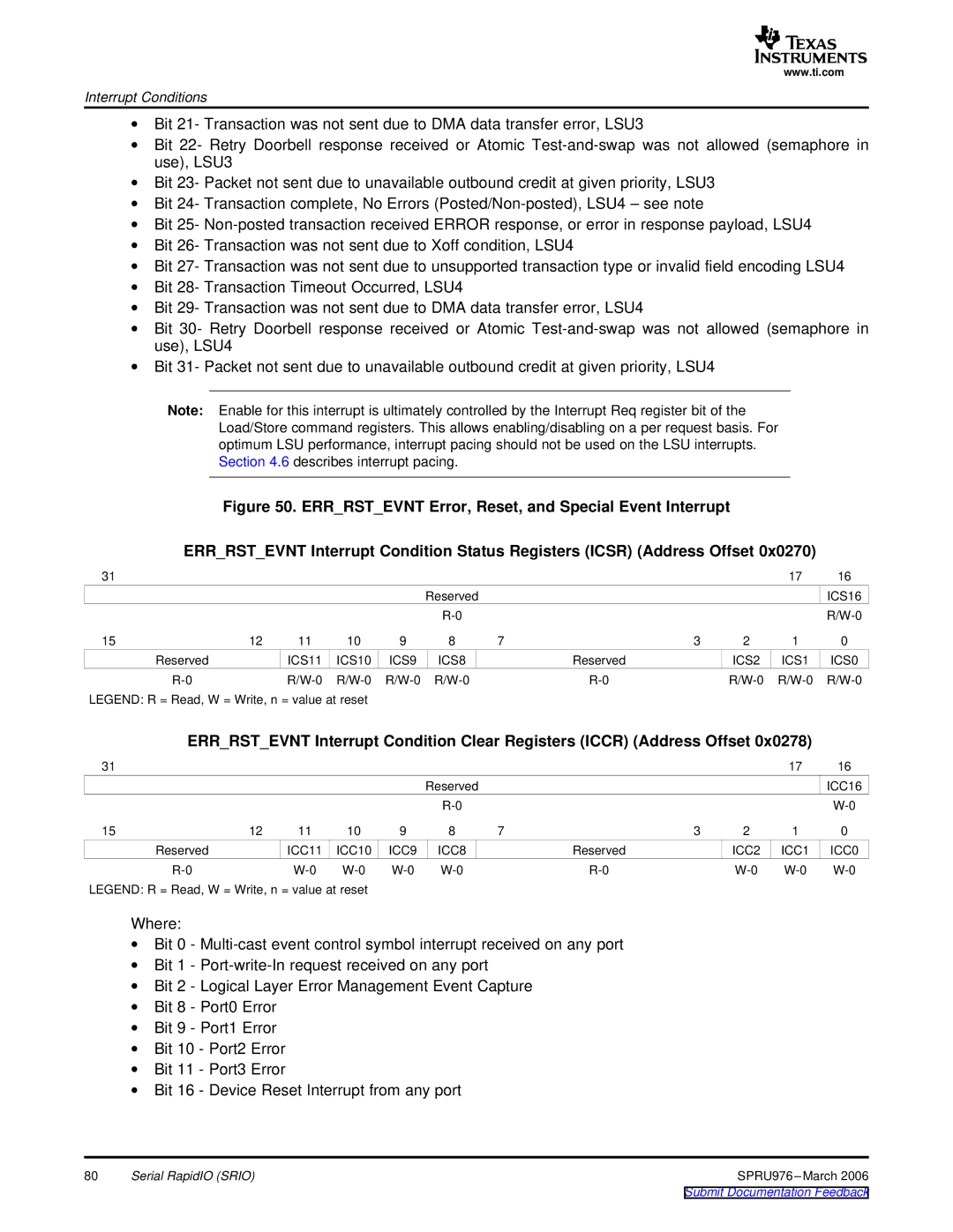
Figure 50. ERR_RST_EVNT Error, Reset, and Special Event Interrupt
ERR_RST_EVNT Interrupt Condition Status Registers (ICSR) (Address Offset 0x0270)
31 |
|
|
|
|
|
|
|
| 17 | 16 |
|
|
|
|
| Reserved |
|
|
|
| ICS16 |
|
|
|
|
|
|
|
|
| ||
15 | 12 | 11 | 10 | 9 | 8 | 7 | 3 | 2 | 1 | 0 |
Reserved |
| ICS11 | ICS10 | ICS9 | ICS8 |
| Reserved | ICS2 | ICS1 | ICS0 |
|
|
LEGEND: R = Read, W = Write, n = value at reset
ERR_RST_EVNT Interrupt Condition Clear Registers (ICCR) (Address Offset 0x0278)
31 |
|
|
|
|
|
|
|
| 17 | 16 |
|
|
|
|
| Reserved |
|
|
|
| ICC16 |
|
|
|
|
|
|
|
|
| ||
15 | 12 | 11 | 10 | 9 | 8 | 7 | 3 | 2 | 1 | 0 |
Reserved |
| ICC11 | ICC10 | ICC9 | ICC8 |
| Reserved | ICC2 | ICC1 | ICC0 |
|
|
LEGEND: R = Read, W = Write, n = value at reset
Where:
∙Bit 0 -
∙Bit 1 -
∙Bit 2 - Logical Layer Error Management Event Capture
∙Bit 8 - Port0 Error
∙Bit 9 - Port1 Error
∙Bit 10 - Port2 Error
∙Bit 11 - Port3 Error
∙Bit 16 - Device Reset Interrupt from any port
80 | Serial RapidIO (SRIO) | SPRU976 |
|
| Submit Documentation Feedback |