www.ti.com
SRIO Functional Description
2.3.6Doorbell
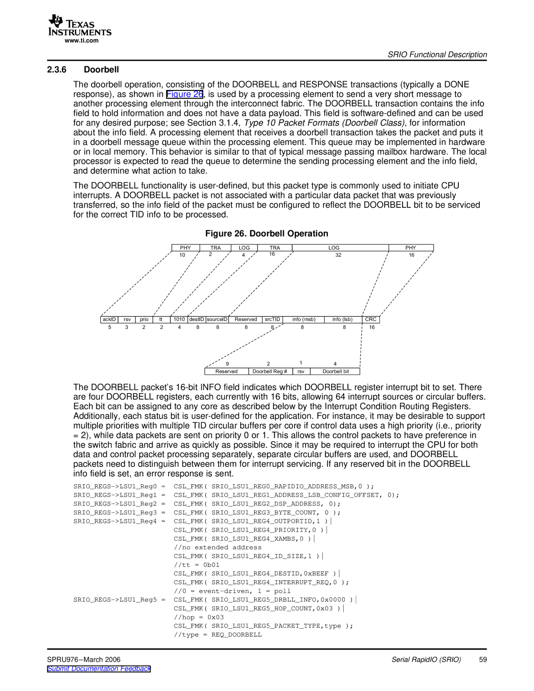
The doorbell operation, consisting of the DOORBELL and RESPONSE transactions (typically a DONE response), as shown in Figure 26, is used by a processing element to send a very short message to another processing element through the interconnect fabric. The DOORBELL transaction contains the info field to hold information and does not have a data payload. This field is
The DOORBELL functionality is
Figure 26. Doorbell Operation
PHY | TRA | LOG | TRA | LOG |
10 | 2 | 4 | 16 | 32 |
PHY
16
acklD | rsv | prio | tt | 1010 | destID | sourcelD | Reserved | srcTID | info |
| info |
| CRC | |||
5 | 3 | 2 | 2 | 4 | 8 | 8 |
| 8 |
| 8 | 8 | 8 | 16 | |||
|
|
|
|
|
| 9 |
|
| 2 | 1 | 4 |
|
| |||
|
|
|
|
|
|
|
|
|
|
|
|
|
|
|
|
|
|
|
|
|
|
| Reserved |
| Doorbell |
| rsv | Doorbell |
|
| |||
The DOORBELL packet’s
Additionally, each status bit is
=2), while data packets are sent on priority 0 or 1. This allows the control packets to have preference in the switch fabric and arrive as quickly as possible. Since it may be required to interrupt the CPU for both data and control packet processing separately, separate circular buffers are used, and DOORBELL packets need to distinguish between them for interrupt servicing. If any reserved bit in the DOORBELL info field is set, an error response is sent.
CSL_FMK( SRIO_LSU1_REG0_RAPIDIO_ADDRESS_MSB,0 ); |
| |
CSL_FMK( SRIO_LSU1_REG1_ADDRESS_LSB_CONFIG_OFFSET, 0); |
| |
CSL_FMK( SRIO_LSU1_REG2_DSP_ADDRESS, 0); |
| |
CSL_FMK( SRIO_LSU1_REG3_BYTE_COUNT, 0 ); |
| |
CSL_FMK( SRIO_LSU1_REG4_OUTPORTID,1 ) |
| |
| CSL_FMK( SRIO_LSU1_REG4_PRIORITY,0 ) |
|
| CSL_FMK( SRIO_LSU1_REG4_XAMBS,0 ) |
|
| //no extended address |
|
| CSL_FMK( SRIO_LSU1_REG4_ID_SIZE,1 ) |
|
| //tt = 0b01 |
|
| CSL_FMK( SRIO_LSU1_REG4_DESTID,0xBEEF ) |
|
| CSL_FMK( SRIO_LSU1_REG4_INTERRUPT_REQ,0 ); |
|
| //0 = |
|
CSL_FMK( SRIO_LSU1_REG5_DRBLL_INFO,0x0000 ) |
| |
| CSL_FMK( SRIO_LSU1_REG5_HOP_COUNT,0x03 ) |
|
| //hop = 0x03 |
|
| CSL_FMK( SRIO_LSU1_REG5_PACKET_TYPE,type ); |
|
| //type = REQ_DOORBELL |
|
SPRU976 | Serial RapidIO (SRIO) | 59 |