www.ti.com
SRIO Functional Description
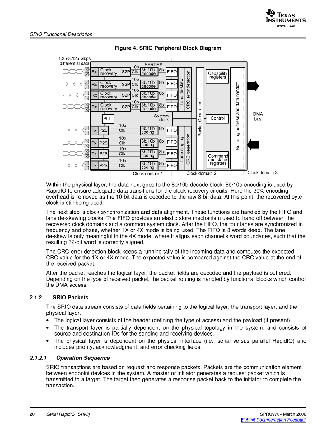
Figure 4. SRIO Peripheral Block Diagram
|
|
|
|
|
|
| |
differential |
| 10b | SERDES |
|
|
| |
|
|
|
|
| |||
| Clock | 8b/10b | 8b |
|
|
| |
Rx | recovery | S2P Clk | decode |
| FIFO |
|
|
Rx | Clock | 10b | 8b/10b | 8b | FIFO |
|
|
recovery | S2P Clk | decode |
|
|
|
| |
| Clock | 10b | 8b/10b | 8b |
|
|
|
Rx | recovery | S2P Clk | decode | 8b | FIFO | Lane | CRC |
Rx | Clock | S2P Clk | 8b/10b | FIFO | |||
|
| 10b |
|
|
|
|
|
| recovery |
| decode |
|
|
|
|
| PLL |
| System |
|
| ||
|
|
| clock |
|
| ||
|
| 10b | 8b/10b | 8b |
|
|
|
Tx | P2S | Clk | FIFO |
|
| ||
|
|
| coding |
|
|
|
|
|
| 10b | 8b/10b | 8b | FIFO |
|
|
Tx | P2S | Clk |
|
| |||
|
|
| coding |
|
|
|
|
|
| 10b | 8b/10b | 8b |
| Lane |
|
Tx | P2S | Clk | FIFO | CRC | |||
|
| 10b | coding |
|
| ||
|
|
|
|
|
|
| |
Tx | P2S | Clk | 8b/10b | 8b | FIFO |
|
|
|
|
| coding |
|
|
|
|
|
| Clock |
|
|
| Clock | |
Packet
Capability
registers
Control
Command and registers
f
feringBuf
DMA bus
Clock
Within the physical layer, the data next goes to the 8b/10b decode block. 8b/10b encoding is used by RapidIO to ensure adequate data transitions for the clock recovery circuits. Here the 20% encoding overhead is removed as the
The next step is clock synchronization and data alignment. These functions are handled by the FIFO and lane
The CRC error detection block keeps a running tally of the incoming data and computes the expected CRC value for the 1X or 4X mode. The expected value is compared against the CRC value at the end of the received packet.
After the packet reaches the logical layer, the packet fields are decoded and the payload is buffered. Depending on the type of received packet, the packet routing is handled by functional blocks which control the DMA access.
2.1.2SRIO Packets
The SRIO data stream consists of data fields pertaining to the logical layer, the transport layer, and the physical layer.
∙The logical layer consists of the header (defining the type of access) and the payload (if present).
∙The transport layer is partially dependent on the physical topology in the system, and consists of source and destination IDs for the sending and receiving devices.
∙The physical layer is dependent on the physical interface (i.e., serial versus parallel RapidIO) and includes priority, acknowledgment, and error checking fields.
2.1.2.1Operation Sequence
SRIO transactions are based on request and response packets. Packets are the communication element between endpoint devices in the system. A master or initiator generates a request packet which is transmitted to a target. The target then generates a response packet back to the initiator to complete the transaction.
20 | Serial RapidIO (SRIO) | SPRU976 |