Texas Instruments TMS320C645x manual Interrupt Generation, Interrupt Pacing

Models: TMS320C645x

1 218
Download 218 pages 2.08 Kb
Page 85
Image 85

www.ti.com

Interrupt Conditions

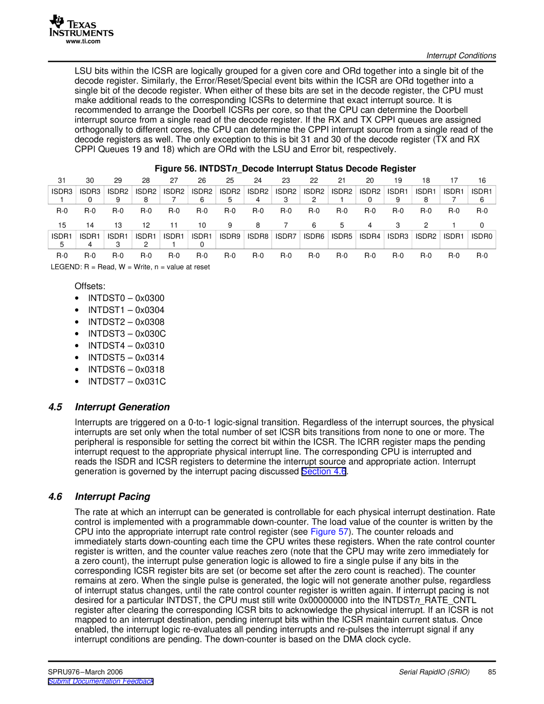
LSU bits within the ICSR are logically grouped for a given core and ORd together into a single bit of the decode register. Similarly, the Error/Reset/Special event bits within the ICSR are ORd together into a single bit of the decode register. When either of these bits are set in the decode register, the CPU must make additional reads to the corresponding ICSRs to determine that exact interrupt source. It is recommended to arrange the Doorbell ICSRs per core, so that the CPU can determine the Doorbell interrupt source from a single read of the decode register. If the RX and TX CPPI queues are assigned orthogonally to different cores, the CPU can determine the CPPI interrupt source from a single read of the decode registers as well. The only exception to this is bit 31 and 30 of the decode register (TX and RX CPPI Queues 19 and 18) which are ORd with the LSU and Error bit, respectively.

Figure 56. INTDSTn_Decode Interrupt Status Decode Register

31

30

29

28

27

26

25

24

23

22

21

20

19

18

17

16

ISDR3

ISDR3

ISDR2

ISDR2

ISDR2

ISDR2

ISDR2

ISDR2

ISDR2

ISDR2

ISDR2

ISDR2

ISDR1

ISDR1

ISDR1

ISDR1

1

0

9

8

7

6

5

4

3

2

1

0

9

8

7

6

R-0

R-0

R-0

R-0

R-0

R-0

R-0

R-0

R-0

R-0

R-0

R-0

R-0

R-0

R-0

R-0

15

14

13

12

11

10

9

8

7

6

5

4

3

2

1

0

ISDR1

ISDR1

ISDR1

ISDR1

ISDR1

ISDR1

ISDR9

ISDR8

ISDR7

ISDR6

ISDR5

ISDR4

ISDR3

ISDR2

ISDR1

ISDR0

5

4

3

2

1

0


R-0

R-0

R-0

R-0

R-0

R-0

R-0

R-0

R-0

R-0

R-0

R-0

R-0

R-0

R-0

R-0

LEGEND: R = Read, W = Write, n = value at reset

Offsets:

INTDST0 – 0x0300

INTDST1 – 0x0304

INTDST2 – 0x0308

INTDST3 – 0x030C

INTDST4 – 0x0310

INTDST5 – 0x0314

INTDST6 – 0x0318

INTDST7 – 0x031C

4.5Interrupt Generation

Interrupts are triggered on a 0-to-1 logic-signal transition. Regardless of the interrupt sources, the physical interrupts are set only when the total number of set ICSR bits transitions from none to one or more. The peripheral is responsible for setting the correct bit within the ICSR. The ICRR register maps the pending interrupt request to the appropriate physical interrupt line. The corresponding CPU is interrupted and reads the ISDR and ICSR registers to determine the interrupt source and appropriate action. Interrupt generation is governed by the interrupt pacing discussed Section 4.6.

4.6Interrupt Pacing

The rate at which an interrupt can be generated is controllable for each physical interrupt destination. Rate control is implemented with a programmable down-counter. The load value of the counter is written by the CPU into the appropriate interrupt rate control register (see Figure 57). The counter reloads and immediately starts down-counting each time the CPU writes these registers. When the rate control counter register is written, and the counter value reaches zero (note that the CPU may write zero immediately for a zero count), the interrupt pulse generation logic is allowed to fire a single pulse if any bits in the corresponding ICSR register bits are set (or become set after the zero count is reached). The counter remains at zero. When the single pulse is generated, the logic will not generate another pulse, regardless of interrupt status changes, until the rate control counter register is written again. If interrupt pacing is not desired for a particular INTDST, the CPU must still write 0x00000000 into the INTDSTn_RATE_CNTL register after clearing the corresponding ICSR bits to acknowledge the physical interrupt. If an ICSR is not mapped to an interrupt destination, pending interrupt bits within the ICSR maintain current status. Once enabled, the interrupt logic re-evaluates all pending interrupts and re-pulses the interrupt signal if any interrupt conditions are pending. The down-counter is based on the DMA clock cycle.

SPRU976 –March 2006

Serial RapidIO (SRIO)

85

Submit Documentation Feedback

Page 85
Image 85
Texas Instruments TMS320C645x manual Interrupt Generation, Interrupt Pacing