www.ti.com
SRIO Functional Description
2.3.2.4SERDES Configuration Example
rdata =
mask = 0x00000FFF;
mdata = (wdata & mask) (rdata & ~mask);
= mdata ; | // 3.125 | Gbps | |||
= mdata ; | // 3.125 | Gbps | |||
= | mdata ; | // | 3.125 | Gbps | |
| = | mdata ; | // | 3.125 | Gbps |
=0x00081101 ; // enable rx, rate 1
=0x00081101 ; // enable rx, rate 1
=0x00081101 ; // enable rx, rate 1
=0x00081101 ; // enable rx, rate 1
=0x00010801 ; // enable tx, rate 1
=0x00010801 ; // enable tx, rate 1
=0x00010801 ; // enable tx, rate 1
=0x00010801 ; // enable tx, rate 1
2.3.3DirectIO
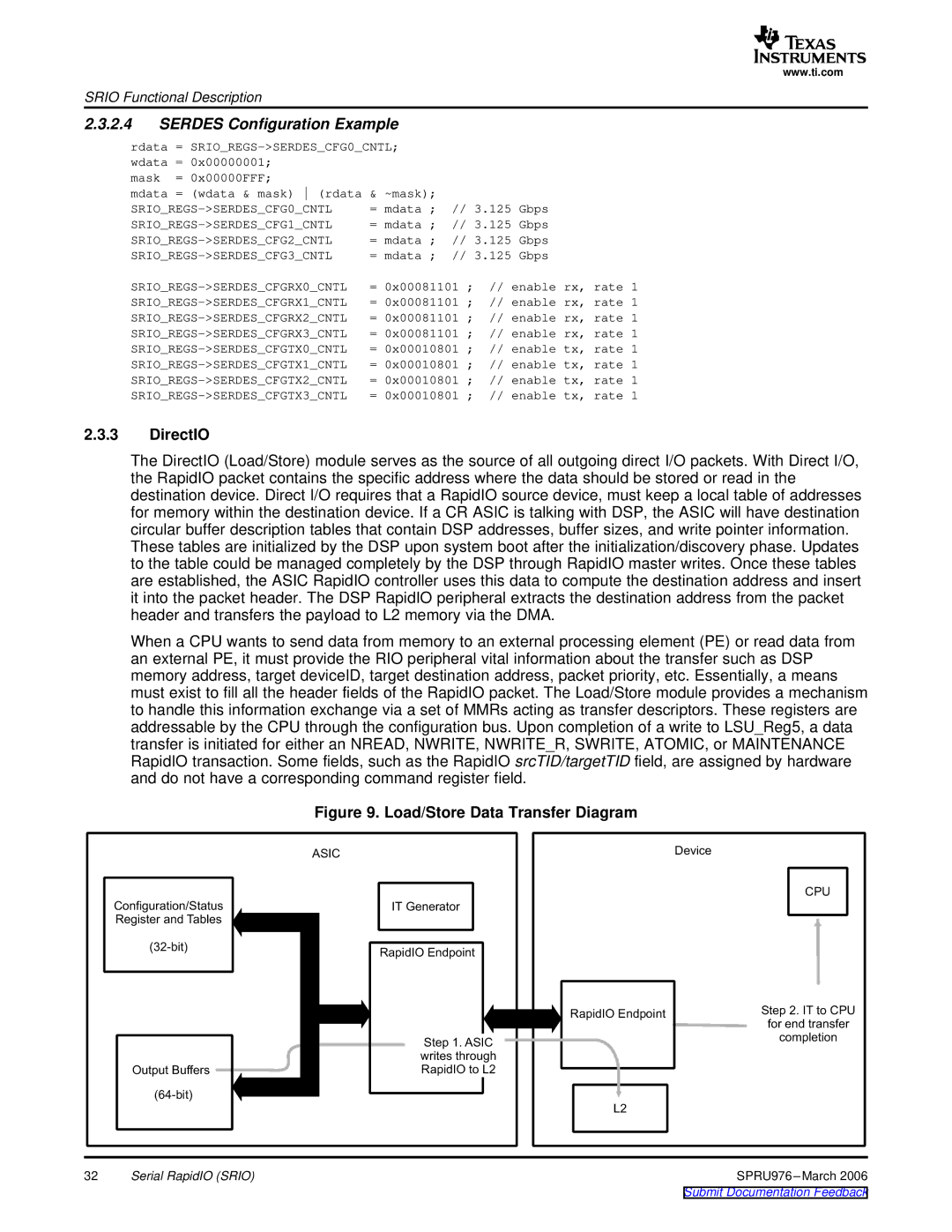
The DirectIO (Load/Store) module serves as the source of all outgoing direct I/O packets. With Direct I/O, the RapidIO packet contains the specific address where the data should be stored or read in the destination device. Direct I/O requires that a RapidIO source device, must keep a local table of addresses for memory within the destination device. If a CR ASIC is talking with DSP, the ASIC will have destination circular buffer description tables that contain DSP addresses, buffer sizes, and write pointer information. These tables are initialized by the DSP upon system boot after the initialization/discovery phase. Updates to the table could be managed completely by the DSP through RapidIO master writes. Once these tables are established, the ASIC RapidIO controller uses this data to compute the destination address and insert it into the packet header. The DSP RapidIO peripheral extracts the destination address from the packet header and transfers the payload to L2 memory via the DMA.
When a CPU wants to send data from memory to an external processing element (PE) or read data from an external PE, it must provide the RIO peripheral vital information about the transfer such as DSP memory address, target deviceID, target destination address, packet priority, etc. Essentially, a means must exist to fill all the header fields of the RapidIO packet. The Load/Store module provides a mechanism to handle this information exchange via a set of MMRs acting as transfer descriptors. These registers are addressable by the CPU through the configuration bus. Upon completion of a write to LSU_Reg5, a data transfer is initiated for either an NREAD, NWRITE, NWRITE_R, SWRITE, ATOMIC, or MAINTENANCE RapidIO transaction. Some fields, such as the RapidIO srcTID/targetTID field, are assigned by hardware and do not have a corresponding command register field.
Figure 9. Load/Store Data Transfer Diagram
|
| ASIC |
|
Configuration/Status | IT Generator |
| |
Register | Tables |
|
|
RapidIO |
| ||
|
|
| |
|
| Step | ASIC |
|
| writes |
|
Output | fers | RapidIO | |
|
| ||
32Serial RapidIO (SRIO)
| Device |
|
|
| CPU |
RapidIO | Step | to |
for |
| |
|
| |
| completion | |
L2 |
|
|
| SPRU976 | |