www.ti.com

SRIO Functional Description

Teardown of an Rx queue causes the following actions:

If teardown is issued by software during the time when the RX state machine is idle, then the state machine will immediately start the teardown procedure:

If the queue to be torn down is in-message (waiting for one or more segments), then the queue will be torn down and reported with the current buffer descriptor (teardown bit set, ownership bit cleared, CC = 100b). All other fields of the buffer descriptor are invalid. The peripheral completes the teardown procedure by clearing the HDP register, setting the CP register to 0xFFFFFFFC, and issuing an interrupt for the given queue. The teardown command register bit is automatically cleared by the peripheral.

If the queue is not in-message, and active (next descriptor available), then the next descriptor will be fetched and updated to report teardown (teardown bit set, ownership bit cleared, CC = 100b). All other fields of the buffer descriptor are invalid. The peripheral completes the teardown procedure by clearing the HDP register, setting the CP register to 0xfffffffC, and issuing an interrupt for the given queue. The teardown command register bit is automatically cleared by the peripheral.

If the queue is not in-message, but inactive (next descriptor unavailable), then no additional buffer descriptor will be written. The HDP register and the CP register remain unchanged. An interrupt is not issued. The teardown command register bit is automatically cleared by the peripheral.

If teardown is issued by software during the time when the RXU state machine is busy, the teardown procedure will be postponed until the state machine is idle.

After the teardown process is complete and the interrupt is serviced by the CPU, the software must re-initialize the RX queue to restart normal operation.

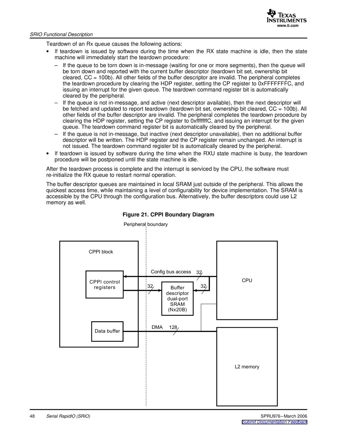
The buffer descriptor queues are maintained in local SRAM just outside of the peripheral. This allows the quickest access time, while maintaining a level of configurability for device implementation. The SRAM is accessible by the CPU through the configuration bus. Alternatively, the buffer descriptors could use L2 memory as well.

Figure 21. CPPI Boundary Diagram


Peripheral


CPPI


Config


32

CPPI control

32


32

registers

Buffer


descriptor


dual-port


SRAM


(Nx20B)


Data buffer

DMA

128


CPU

L2

48

Serial RapidIO (SRIO)

SPRU976 –March 2006

Submit Documentation Feedback

Page 48
Image 48
Texas Instruments TMS320C645x manual Cppi Boundary Diagram