www.ti.com
SRIO Functional Description
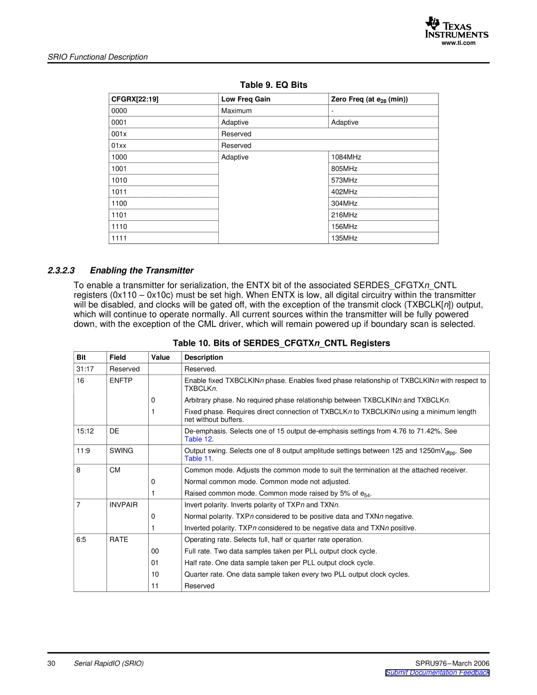
Table 9. EQ Bits
CFGRX[22:19] | Low Freq Gain | Zero Freq (at e28 (min)) |
0000 | Maximum | - |
0001 | Adaptive | Adaptive |
001x | Reserved |
|
01xx | Reserved |
|
1000 | Adaptive | 1084MHz |
1001 |
| 805MHz |
1010 |
| 573MHz |
1011 |
| 402MHz |
1100 |
| 304MHz |
1101 |
| 216MHz |
1110 |
| 156MHz |
1111 |
| 135MHz |
2.3.2.3Enabling the Transmitter
To enable a transmitter for serialization, the ENTX bit of the associated SERDES_CFGTXn_CNTL registers (0x110 – 0x10c) must be set high. When ENTX is low, all digital circuitry within the transmitter will be disabled, and clocks will be gated off, with the exception of the transmit clock (TXBCLK[n]) output, which will continue to operate normally. All current sources within the transmitter will be fully powered down, with the exception of the CML driver, which will remain powered up if boundary scan is selected.
|
|
| Table 10. Bits of SERDES_CFGTXn_CNTL Registers |
Bit | Field | Value | Description |
31:17 | Reserved |
| Reserved. |
16 | ENFTP |
| Enable fixed TXBCLKINn phase. Enables fixed phase relationship of TXBCLKINn with respect to |
|
|
| TXBCLKn. |
|
| 0 | Arbitrary phase. No required phase relationship between TXBCLKINn and TXBCLKn. |
|
| 1 | Fixed phase. Requires direct connection of TXBCLKn to TXBCLKINn using a minimum length |
|
|
| net without buffers. |
15:12 | DE |
| |
|
|
| Table 12. |
11:9 | SWING |
| Output swing. Selects one of 8 output amplitude settings between 125 and 1250mVdfpp. See |
|
|
| Table 11. |
8 | CM |
| Common mode. Adjusts the common mode to suit the termination at the attached receiver. |
|
| 0 | Normal common mode. Common mode not adjusted. |
|
| 1 | Raised common mode. Common mode raised by 5% of e54. |
7 | INVPAIR |
| Invert polarity. Inverts polarity of TXPn and TXNn. |
|
| 0 | Normal polarity. TXPn considered to be positive data and TXNn negative. |
|
| 1 | Inverted polarity. TXPn considered to be negative data and TXNn positive. |
6:5 | RATE |
| Operating rate. Selects full, half or quarter rate operation. |
|
| 00 | Full rate. Two data samples taken per PLL output clock cycle. |
|
| 01 | Half rate. One data sample taken per PLL output clock cycle. |
|
| 10 | Quarter rate. One data sample taken every two PLL output clock cycles. |
|
| 11 | Reserved |
30 | Serial RapidIO (SRIO) | SPRU976 |
|
| Submit Documentation Feedback |