www.ti.com
|
|
|
|
|
|
|
|
| SRIO Functional Description | ||
|
|
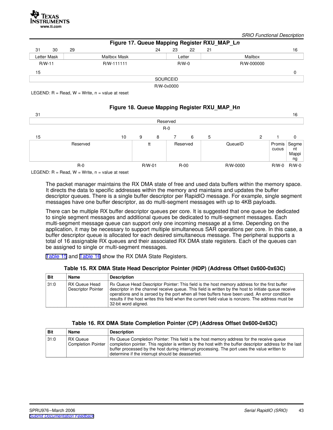
| Figure 17. Queue Mapping Register RXU_MAP_Ln |
|
| ||||||
31 | 30 | 29 |
|
| 24 | 23 | 22 | 21 |
|
| 16 |
Letter Mask |
| Mailbox Mask |
|
| Letter |
|
| Mailbox |
|
| |
|
|
|
|
|
|
| |||||
15 |
|
|
|
|
|
|
|
|
|
| 0 |
|
|
|
|
| SOURCEID |
|
|
|
|
| |
|
|
|
|
|
|
|
|
|
| ||
LEGEND: R = Read, W = Write, n = value at reset |
|
|
|
|
|
|
|
| |||
|
|
| Figure 18. Queue Mapping Register RXU_MAP_Hn |
|
| ||||||
31 |
|
|
|
|
|
|
|
|
|
| 16 |
|
|
|
|
| Reserved |
|
|
|
|
| |
|
|
|
|
|
|
|
|
|
|
| |
15 |
|
| 10 | 9 | 8 | 7 | 6 | 5 | 2 | 1 | 0 |
|
| Reserved |
|
| tt | Reserved |
| QueueID | Promis | Segme | |
|
|
|
|
|
|
|
|
|
| cuous | nt |
|
|
|
|
|
|
|
|
|
|
| Mappi |
|
|
|
|
|
|
|
|
|
|
| ng |
|
|
|
|
|
| ||||||
LEGEND: R = Read, W = Write, n = value at reset |
|
|
|
|
|
|
|
| |||
The packet manager maintains the RX DMA state of free and used data buffers within the memory space. It directs the data to specific addresses within the memory and maintains and updates the buffer descriptor queues. There is a single buffer descriptor per RapidIO message. For example, single segment messages have one buffer descriptor, as do
There can be multiple RX buffer descriptor queues per core. It is suggested that one queue be dedicated to single segment messages and additional queues be dedicated to
Table 15 and Table 16 show the RX DMA State Registers.
Table 15. RX DMA State Head Descriptor Pointer (HDP) (Address Offset
Bit | Name | Description |
31:0 | RX Queue Head | Rx Queue Head Descriptor Pointer: This field is the host memory address for the first buffer |
| Descriptor Pointer | descriptor in the channel receive queue. This field is written by the host to initiate queue receive |
|
| operations and is zeroed by the port when all free buffers have been used. An error condition |
|
| results if the host writes this field when the current field value is nonzero. The address must be |
|
|
Table 16. RX DMA State Completion Pointer (CP) (Address Offset
Bit | Name | Description |
31:0 | RX Queue | Rx Queue Completion Pointer: This field is the host memory address for the receive queue |
| Completion Pointer | completion pointer. This register is written by the host with the buffer descriptor address for the last |
|
| buffer processed by the host during interrupt processing. The port uses the value written to |
|
| determine if the interrupt should be deasserted. |
SPRU976 | Serial RapidIO (SRIO) | 43 |