www.ti.com
SRIO Functional Description
Table 24. Enable and Enable Status Bit Field Descriptions (continued)
Name | Bit | Access | Description | |
BLK8_EN_STAT | 0 | R | Indicates state of BLK8_EN reset signal. | |
|
|
| 0 | = Logical block 8 in reset and clock is off |
|
|
| 1 | = Logical block 8 enabled and clocking |
The GBL_EN register is implemented with a single ENABLE bit. This bit is logically ORd with the reset input to the module and is fanned out to all logical blocks within the peripheral.
2.3.9.3Software Shutdown Details
Power consumption must be minimized for all logical blocks that are in shutdown. In addition to simply asserting the appropriate reset signal to each logical block within the peripheral, clocks are gated off to the corresponding logical block as well. Clocks are allowed to run for 32 clock cycles, which is necessary to fully reset each logical block. When the appropriate logical block is fully reset, the clock input to that subblock is gated off.
When a block is disabled, the reset control block turns off the peripheral with the following sequence:
1.Deassert GBL_EN signal or appropriate BLKn_EN signal, which effectively resets all subblocks or the given subblock.
2.Wait 32 clock cycles to guarantee full reset.
3.Gate the input clock to the logical block(s). When the full shutdown procedure is complete, the BLKn_EN_STAT bits and/or the GBL_EN_STAT bit contain 0.
The opposite is done for software controlled enabling of a logical block:
1.Assert the BLK_EN signal to release the logical block from reset.
2.Turn on the logical block. When the full
When using the GBL_EN to shutdown/reset the peripheral, it is important to first stop all
1.Stop all RapidIO source transactions, including LSU and TXU operations. This essentially means waiting for the LSU or TXU CC field to be set, or, alternatively, teardown of the active TXU queues.
2.Disable the PEREN bit of the PCR register to stop all new logical layer transactions.
3.Wait the number of clock cycles required to finish any current DMA transfer.
4.Deassert GBL_EN.
2.3.10Emulation
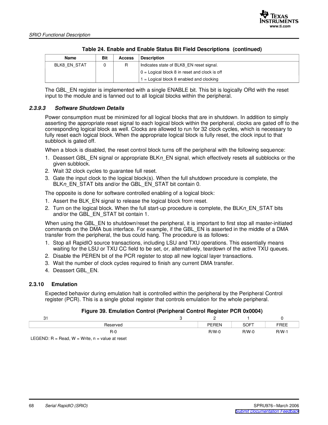
Expected behavior during emulation halt is controlled within the peripheral by the Peripheral Control register (PCR). This is a single global register that controls emulation for the whole peripheral.
Figure 39. Emulation Control (Peripheral Control Register PCR 0x0004)
31 | 3 | 2 | 1 | 0 |
Reserved |
| PEREN | SOFT | FREE |
|
LEGEND: R = Read, W = Write, n = value at reset
68 | Serial RapidIO (SRIO) | SPRU976 |
|
| Submit Documentation Feedback |