www.ti.com
SRIO Functional Description
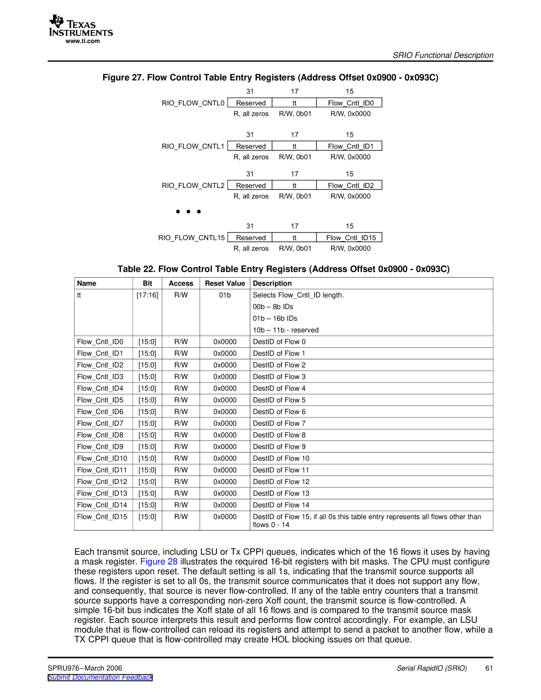
Figure 27. Flow Control Table Entry Registers (Address Offset 0x0900 - 0x093C)
|
|
|
|
|
| 31 | 17 |
| 15 |
|
|
|
|
|
|
|
|
| |||
|
| RIO_FLOW_CNTL0 |
| Reserved | tt |
| Flow_Cntl_ID0 |
| ||
|
|
|
|
| R, |
| R/W, | R/W, | ||
|
|
|
|
|
| 31 | 17 |
| 15 |
|
|
|
|
|
|
| |||||
|
| RIO_FLOW_CNTL1 |
| Reserved | tt |
| Flow_Cntl_ID1 |
| ||
|
|
|
|
| R, |
| R/W, | R/W, | ||
|
|
|
|
|
| 31 | 17 |
| 15 |
|
|
|
|
|
|
| |||||
|
| RIO_FLOW_CNTL2 |
| Reserved | tt |
| Flow_Cntl_ID2 |
| ||
|
|
|
|
| R, |
| R/W, | R/W, | ||
|
|
|
|
|
| 31 | 17 |
| 15 |
|
|
|
|
|
|
| |||||
|
| RIO_FLOW_CNTL15 |
| Reserved | tt |
| Flow_Cntl_ID15 |
| ||
|
|
|
|
| R, |
| R/W, | R/W, | ||
Table 22. Flow Control Table Entry Registers (Address Offset 0x0900 - 0x093C) | ||||||||||
Name | Bit | Access | Reset Value | Description |
|
| ||||
tt | [17:16] | R/W | 01b |
| Selects Flow_Cntl_ID length. | |||||
|
|
|
|
|
| 00b – 8b IDs |
|
| ||
|
|
|
|
|
| 01b – 16b IDs |
|
| ||
|
|
|
|
|
| 10b – 11b - reserved |
|
| ||
Flow_Cntl_ID0 | [15:0] | R/W | 0x0000 | DestID of Flow 0 |
|
| ||||
Flow_Cntl_ID1 | [15:0] | R/W | 0x0000 | DestID of Flow 1 |
|
| ||||
Flow_Cntl_ID2 | [15:0] | R/W | 0x0000 | DestID of Flow 2 |
|
| ||||
Flow_Cntl_ID3 | [15:0] | R/W | 0x0000 | DestID of Flow 3 |
|
| ||||
Flow_Cntl_ID4 | [15:0] | R/W | 0x0000 | DestID of Flow 4 |
|
| ||||
Flow_Cntl_ID5 | [15:0] | R/W | 0x0000 | DestID of Flow 5 |
|
| ||||
Flow_Cntl_ID6 | [15:0] | R/W | 0x0000 | DestID of Flow 6 |
|
| ||||
Flow_Cntl_ID7 | [15:0] | R/W | 0x0000 | DestID of Flow 7 |
|
| ||||
Flow_Cntl_ID8 | [15:0] | R/W | 0x0000 | DestID of Flow 8 |
|
| ||||
Flow_Cntl_ID9 | [15:0] | R/W | 0x0000 | DestID of Flow 9 |
|
| ||||
Flow_Cntl_ID10 | [15:0] | R/W | 0x0000 | DestID of Flow 10 |
|
| ||||
Flow_Cntl_ID11 | [15:0] | R/W | 0x0000 | DestID of Flow 11 |
|
| ||||
Flow_Cntl_ID12 | [15:0] | R/W | 0x0000 | DestID of Flow 12 |
|
| ||||
Flow_Cntl_ID13 | [15:0] | R/W | 0x0000 | DestID of Flow 13 |
|
| ||||
Flow_Cntl_ID14 | [15:0] | R/W | 0x0000 | DestID of Flow 14 |
|
| ||||
Flow_Cntl_ID15 | [15:0] | R/W | 0x0000 | DestID of Flow 15, if all 0s this table entry represents all flows other than | ||||||
|
|
|
|
|
| flows 0 - 14 |
|
| ||
Each transmit source, including LSU or Tx CPPI queues, indicates which of the 16 flows it uses by having a mask register. Figure 28 illustrates the required
SPRU976 | Serial RapidIO (SRIO) | 61 |