www.ti.com
SRIO Functional Description
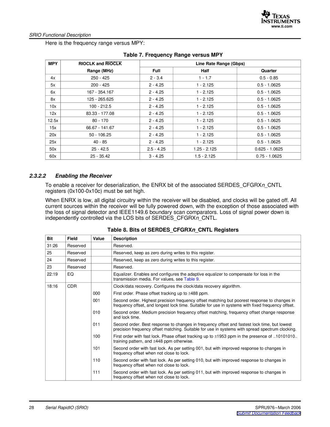
Here is the frequency range versus MPY:
Table 7. Frequency Range versus MPY
MPY | RIOCLK and RIOCLK |
| Line Rate Range (Gbps) |
| ||
| Range (MHz) | Full | Half | Quarter | ||
4x | 250 - 425 | 2 - 3.4 | 1 - 1.7 | 0.5 - 0.85 | ||
5x | 200 - 425 | 2 - 4.25 | 1 - 2.125 | 0.5 - 1.0625 | ||
6x | 167 | - 354.167 | 2 - 4.25 | 1 - 2.125 | 0.5 - 1.0625 | |
8x | 125 | - 265.625 | 2 - 4.25 | 1 - 2.125 | 0.5 - 1.0625 | |
10x | 100 - 212.5 | 2 - 4.25 | 1 - 2.125 | 0.5 - 1.0625 | ||
12x | 83.33 | - 177.08 | 2 - 4.25 | 1 - 2.125 | 0.5 - 1.0625 | |
12.5x | 80 | - 170 | 2 - 4.25 | 1 - 2.125 | 0.5 - 1.0625 | |
15x | 66.67 | - 141.67 | 2 - 4.25 | 1 - 2.125 | 0.5 - 1.0625 | |
20x | 50 | - 106.25 | 2 - 4.25 | 1 - 2.125 | 0.5 - 1.0625 | |
25x | 40 - 85 | 2 - 4.25 | 1 - 2.125 | 0.5 - 1.0625 | ||
50x | 25 - 42.5 | 2.5 - 4.25 | 1.25 - 2.125 | 0.625 - 1.0625 | ||
60x | 25 - 35.42 | 3 - 4.25 | 1.5 - 2.125 | 0.75 - 1.0625 | ||
2.3.2.2Enabling the Receiver
To enable a receiver for deserialization, the ENRX bit of the associated SERDES_CFGRXn_CNTL registers
When ENRX is low, all digital circuitry within the receiver will be disabled, and clocks will be gated off. All current sources within the receiver will be fully powered down, with the exception of those associated with the loss of signal detector and IEEE1149.6 boundary scan comparators. Loss of signal power down is independently controlled via the LOS bits of SERDES_CFGRXn_CNTL.
|
|
| Table 8. Bits of SERDES_CFGRXn_CNTL Registers |
Bit | Field | Value | Description |
31:26 | Reserved |
| Reserved. |
25 | Reserved |
| Reserved, keep as zero during writes to this register. |
24 | Reserved |
| Reserved, keep as zero during writes to this register. |
23 | Reserved |
| Reserved. |
22:19 | EQ |
| Equalizer. Enables and configures the adaptive equalizer to compensate for loss in the |
|
|
| transmission media. For values, see Table 9. |
18:16 | CDR |
| Clock/data recovery. Configures the clock/data recovery algorithm. |
|
| 000 | First order. Phase offset tracking up to ±488 ppm. |
|
| 001 | Second order. Highest precision frequency offset matching but poorest response to changes in |
|
|
| frequency offset, and longest lock time. Suitable for use in systems with fixed frequency offset. |
|
| 010 | Second order. Medium precision frequency offset matching, frequency offset change response |
|
|
| and lock time. |
011Second order. Best response to changes in frequency offset and fastest lock time, but lowest precision frequency offset matching. Suitable for use in systems with spread spectrum clocking.
100First order with fast lock. Phase offset tracking up to ±1953 ppm in the presence of ..10101010.. training pattern, and ±448 ppm otherwise.
101Second order with fast lock. As per setting 001, but with improved response to changes in frequency offset when not close to lock.
110Second order with fast lock. As per setting 010, but with improved response to changes in frequency offset when not close to lock.
111Second order with fast lock. As per setting 011, but with improved response to changes in frequency offset when not close to lock.
28 | Serial RapidIO (SRIO) | SPRU976 |