www.ti.com

SRIO Functional Description

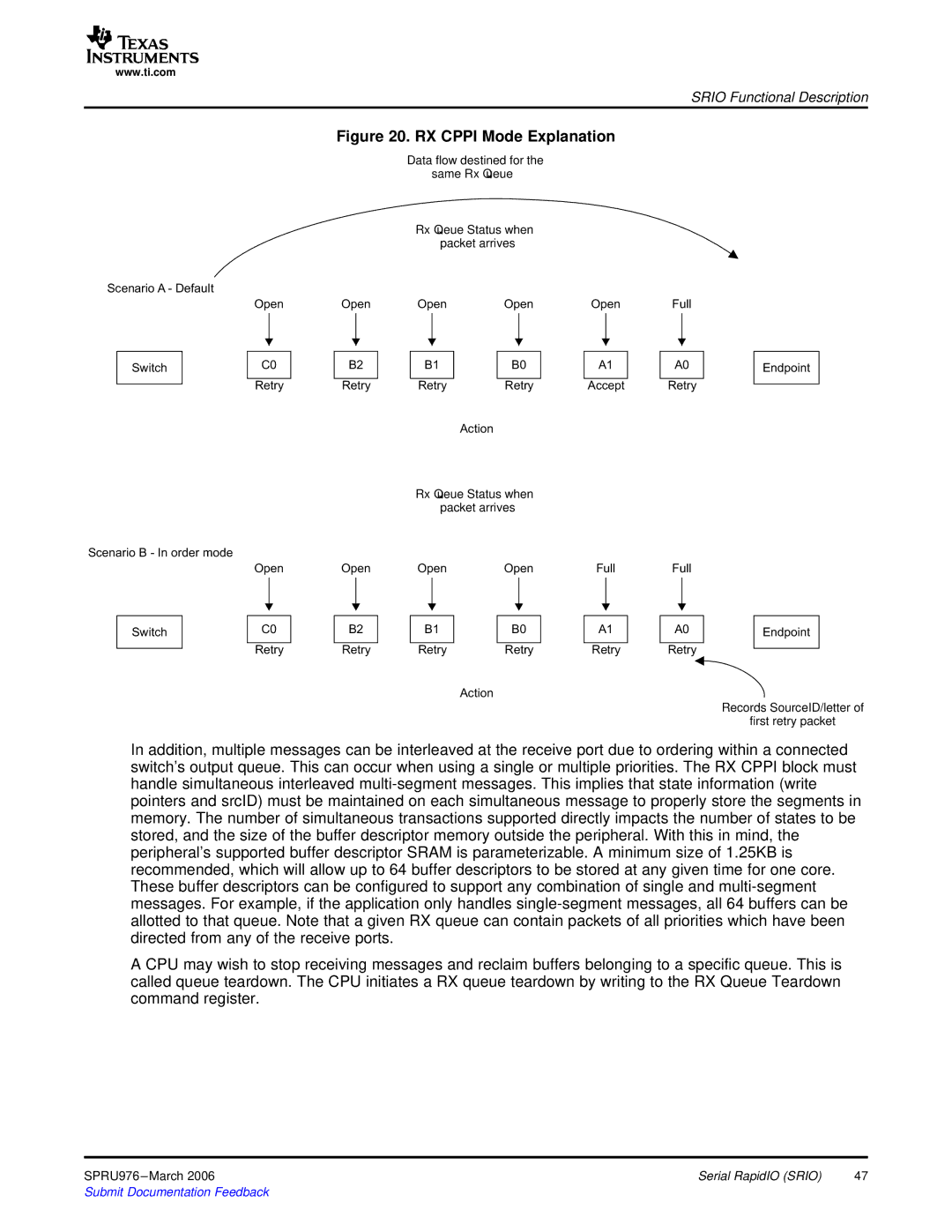
Figure 20. RX CPPI Mode Explanation

Scenario A -

Switch

Scenario

Switch

Open

C0

Retry

Open

C0

Retry

Open

B2

Retry

Open

B2

Retry

Data same

Rx

packet

Open

B1

Retry

Action

Rx

packet

Open

B1

Retry

Action

Open

B0

Retry

Open

B0

Retry

Open

A1

Accept

Full

A1

Retry

Full

A0

Retry

Full

A0

Retry

Endpoint

Endpoint

Records first

In addition, multiple messages can be interleaved at the receive port due to ordering within a connected switch’s output queue. This can occur when using a single or multiple priorities. The RX CPPI block must handle simultaneous interleaved multi-segment messages. This implies that state information (write pointers and srcID) must be maintained on each simultaneous message to properly store the segments in memory. The number of simultaneous transactions supported directly impacts the number of states to be stored, and the size of the buffer descriptor memory outside the peripheral. With this in mind, the peripheral’s supported buffer descriptor SRAM is parameterizable. A minimum size of 1.25KB is recommended, which will allow up to 64 buffer descriptors to be stored at any given time for one core. These buffer descriptors can be configured to support any combination of single and multi-segment messages. For example, if the application only handles single-segment messages, all 64 buffers can be allotted to that queue. Note that a given RX queue can contain packets of all priorities which have been directed from any of the receive ports.

A CPU may wish to stop receiving messages and reclaim buffers belonging to a specific queue. This is called queue teardown. The CPU initiates a RX queue teardown by writing to the RX Queue Teardown command register.

SPRU976 –March 2006

Serial RapidIO (SRIO)

47

Submit Documentation Feedback

Page 47
Image 47
Texas Instruments TMS320C645x manual RX Cppi Mode Explanation