www.ti.com
SRIO Functional Description
2.3.12Bootload Capability
2.3.12.1Configuration
It is assumed that an external device will initiate the bootload data transfer and master the DMA interface. Upon reset, the following sequence of events must occur:
1.DSP is placed in SRIO boot mode by HW mode pins.
2.Host takes DSP out of reset (POR or RST). The peripheral’s state machines and registers are reset.
3.Internal
–Choice of 4 pin selectable configurations
–Optionally, I2C boot can be used to configure SRIO
4.DSP executes idle instruction.
5.RapidIO ports send Idle control symbols to train PHYs.
6.Host enabled to explore system with RapidIO Maintenance packets.
7.Host identifies, enumerates and initializes the RapidIO device.
8.Host controller configures DSP peripherals through maintenance packets.
–SRIO Device IDs are set for DSPs (either by pin strapping or by host manipulation)
9.Boot Code sent from host controller to DSP L2 memory base address via NWRITE.
10.DSP CPU is awakened by an interrupt such as a RapidIO DOORBELL packet.
11.Boot Code is executed and normal operation follows.
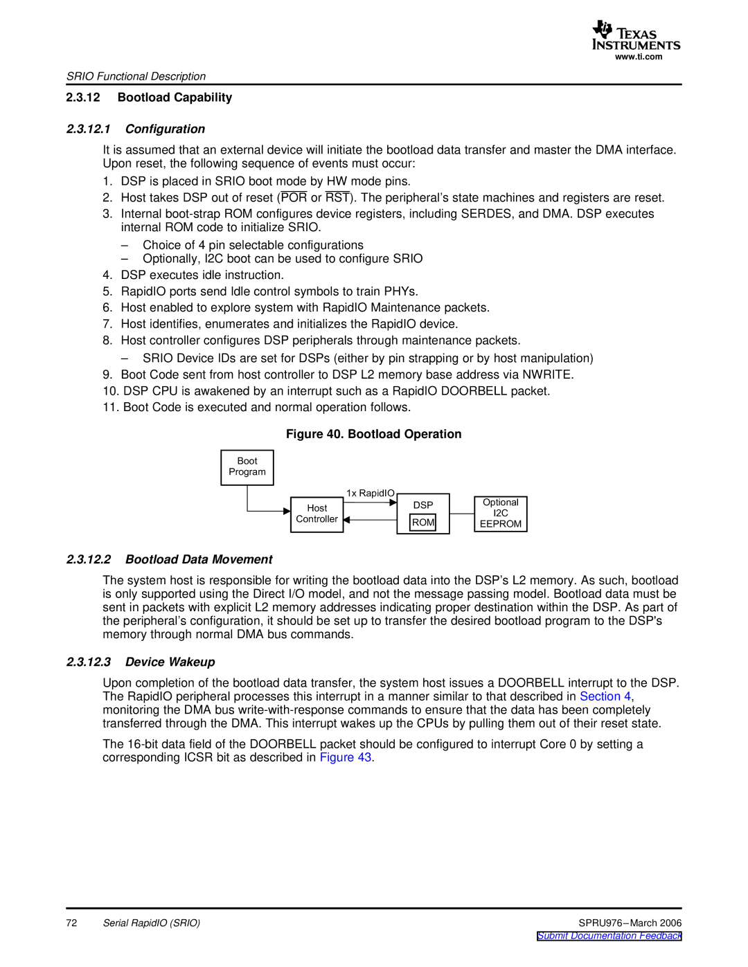
Figure 40. Bootload Operation
Boot
Program
1x
Host
Controller
DSP
ROM
Optional
I2C
EEPROM
2.3.12.2Bootload Data Movement
The system host is responsible for writing the bootload data into the DSP’s L2 memory. As such, bootload is only supported using the Direct I/O model, and not the message passing model. Bootload data must be sent in packets with explicit L2 memory addresses indicating proper destination within the DSP. As part of the peripheral’s configuration, it should be set up to transfer the desired bootload program to the DSP's memory through normal DMA bus commands.
2.3.12.3Device Wakeup
Upon completion of the bootload data transfer, the system host issues a DOORBELL interrupt to the DSP. The RapidIO peripheral processes this interrupt in a manner similar to that described in Section 4, monitoring the DMA bus
The
72 | Serial RapidIO (SRIO) | SPRU976 |