www.ti.com
Interrupt Conditions
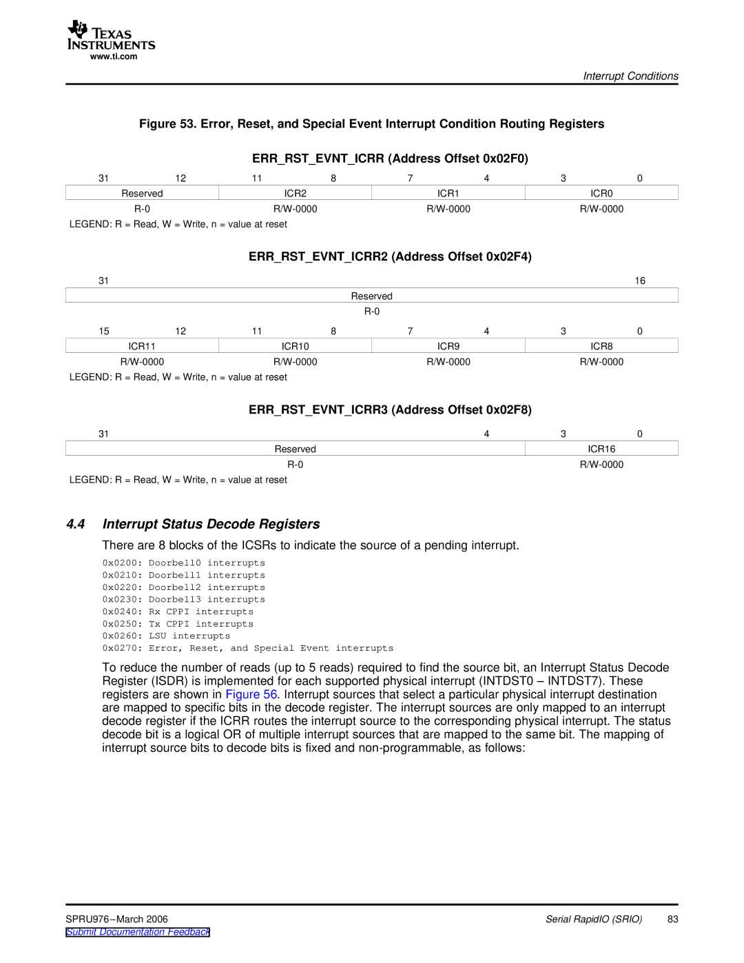
Figure 53. Error, Reset, and Special Event Interrupt Condition Routing Registers
ERR_RST_EVNT_ICRR (Address Offset 0x02F0)
31 | 12 | 11 | 8 | 7 | 4 | 3 | 0 |
| Reserved |
| ICR2 | ICR1 |
|
| ICR0 |
|
|
|
|
LEGEND: R = Read, W = Write, n = value at reset
ERR_RST_EVNT_ICRR2 (Address Offset 0x02F4)
31 |
|
|
|
|
|
| 16 |
|
|
|
| Reserved |
|
|
|
|
|
|
|
|
|
| |
15 | 12 | 11 | 8 | 7 | 4 | 3 | 0 |
| ICR11 |
| ICR10 |
| ICR9 |
| ICR8 |
|
|
|
|
LEGEND: R = Read, W = Write, n = value at reset
ERR_RST_EVNT_ICRR3 (Address Offset 0x02F8)
31 | 4 | 3 | 0 |
Reserved |
|
| ICR16 |
|
|
LEGEND: R = Read, W = Write, n = value at reset
4.4Interrupt Status Decode Registers
There are 8 blocks of the ICSRs to indicate the source of a pending interrupt.
0x0200: Doorbell0 interrupts
0x0210: Doorbell1 interrupts
0x0220: Doorbell2 interrupts
0x0230: Doorbell3 interrupts
0x0240: Rx CPPI interrupts
0x0250: Tx CPPI interrupts
0x0260: LSU interrupts
0x0270: Error, Reset, and Special Event interrupts
To reduce the number of reads (up to 5 reads) required to find the source bit, an Interrupt Status Decode Register (ISDR) is implemented for each supported physical interrupt (INTDST0 – INTDST7). These registers are shown in Figure 56. Interrupt sources that select a particular physical interrupt destination are mapped to specific bits in the decode register. The interrupt sources are only mapped to an interrupt decode register if the ICRR routes the interrupt source to the corresponding physical interrupt. The status decode bit is a logical OR of multiple interrupt sources that are mapped to the same bit. The mapping of interrupt source bits to decode bits is fixed and
SPRU976 | Serial RapidIO (SRIO) | 83 |