www.ti.com
SRIO Functional Description
If a
If a RX message’s length is greater than that of the targeted buffer descriptor, an ERROR response is sent back to the source device. In addition, the DSP is notified with the use of the CC field of the RX CPPI buffer descriptor, described as follows. This situation can result from a DSP software error (misallocating a buffer for the queue), or as a result of sender error (sending to a wrong mailbox).
An Rx transaction timeout is used by all
The buffer descriptor points to the corresponding data buffer in memory and also points to the next buffer descriptor in the queue. As segments of a received message arrive, the msgseg field of each segment is monitored to detect the completion of the received message. Once a full message is received, the OWNERSHIP bit is cleared in the packet’s buffer descriptor to give control to the host. At this point, a host interrupt is issued. This interface works with programmable interrupt rate control, as discussed in
Figure 57. There is an ICSR bit for each supported queue, as shown in Figure 47. On interrupt, the CPU processes the RX buffer queue, detecting received packets by the status of the OWNERSHIP bit in each buffer descriptor. The host processes the RX queue until it reaches a buffer descriptor with a set OWNERSHIP bit, or set EOQ bit. Once processing is complete, the host updates the RX DMA State Completion Pointer, allowing the peripheral to reuse the buffer.
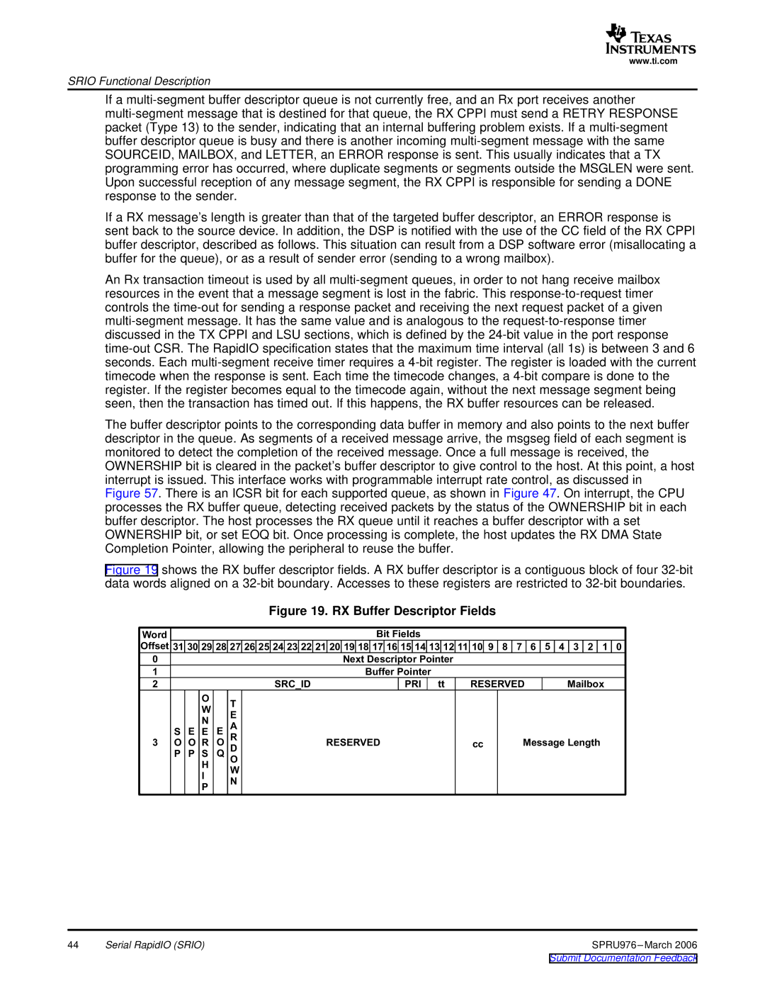
Figure 19 shows the RX buffer descriptor fields. A RX buffer descriptor is a contiguous block of four 32-bit data words aligned on a 32-bit boundary. Accesses to these registers are restricted to 32-bit boundaries.
Figure 19. RX Buffer Descriptor Fields
Word |
|
|
|
|
|
|
|
|
|
|
|
|
|
| Bit |
|
|
|
|
|
|
|
|
|
|
|
|
| |||||
Offset | 31 | 30 | 29 | 28 | 27 | 26 | 25 | 24 | 23 | 22 | 21 | 20 | 19 | 18 | 17 | 16 | 15 | 14 | 13 | 12 | 11 | 10 | 9 | 8 | 7 |
| 6 | 5 | 4 | 3 | 2 | 1 | 0 |
0 |
|
|
|
|
|
|
|
|
|
|
|
| Next |
|
|
|
|
|
|
|
|
|
|
|
|
| |||||||
1 |
|
|
|
|
|
|
|
|
|
|
|
|
| Buffer |
|
|
|
|
|
|
|
|
|
|
|
|
| ||||||
2 |
|
|
|
|
|
|
| SRC_ID |
|
|
|
|
|
| PRI | tt |
| RESERVED |
|
| Mailbox |
| |||||||||||
|
|
| O |
| T |
|
|
|
|
|
|
|
|
|
|
|
|
|
|
|
|
|
|
|
|
|
|
|
|
|
|
|
|
|
|
| W |
|
|
|
|
|
|
|
|
|
|
|
|
|
|
|
|
|
|
|
|
|
|
|
|
|
|
|
|
| |
|
|
|
| E |
|
|
|
|
|
|
|
|
|
|
|
|
|
|
|
|
|
|
|
|
|
|
|
|
|
|
|
| |
|
|
| N |
|
|
|
|
|
|
|
|
|
|
|
|
|
|
|
|
|
|
|
|
|
|
|
|
|
|
|
|
| |
|
|
|
| A |
|
|
|
|
|
|
|
|
|
|
|
|
|
|
|
|
|
|
|
|
|
|
|
|
|
|
|
| |
| S | E | E | E |
|
|
|
|
|
|
|
|
|
|
|
|
|
|
|
|
|
|
|
|
|
|
|
|
|
|
|
| |
3 | O | O | R | O | R |
|
|
|
|
| RESERVED |
| cc |
|
| Message |
|
|
|
| |||||||||||||
| P | P | S | Q | D |
|
|
|
|
|
|
|
|
|
|
|
|
|
|
|
|
|
|
|
|
|
|
|
|
|
|
|
|
|
|
| H |
| O |
|
|
|
|
|
|
|
|
|
|
|
|
|
|
|
|
|
|
|
|
|
|
|
|
|
|
|
|
|
|
|
| W |
|
|
|
|
|
|
|
|
|
|
|
|
|
|
|
|
|
|
|
|
|
|
|
|
|
|
|
| |
|
|
| I |
|
|
|
|
|
|
|
|
|
|
|
|
|
|
|
|
|
|
|
|
|
|
|
|
|
|
|
|
| |
|
|
|
| N |
|
|
|
|
|
|
|
|
|
|
|
|
|
|
|
|
|
|
|
|
|
|
|
|
|
|
|
| |
|
|
| P |
|
|
|
|
|
|
|
|
|
|
|
|
|
|
|
|
|
|
|
|
|
|
|
|
|
|
|
|
| |
|
|
|
|
|
|
|
|
|
|
|
|
|
|
|
|
|
|
|
|
|
|
|
|
|
|
|
|
|
|
|
|
| |
|
|
|
|
|
|
|
|
|
|
|
|
|
|
|
|
|
|
|
|
|
|
|
|
|
|
|
|
|
|
|
|
|
|
44 | Serial RapidIO (SRIO) | SPRU976 |