Test the System
- status system |
|
|
|
|
| SPE B | |||
|
|
| SYSTEM STATUS | CABINET | 1 |
|
|
| |
|
|
| SELECT | SPE ALARMS | TONE/ | SERVICE SYSTEM | SYSTEM | ||
SPE | MODE |
| SWITCH | MAJOR | MINOR | CLOCK | STATE | CLOCK | TONE |
1A | standby |
| auto | 1 | 0 | 1A | in | standby standby | |
1B | active |
| auto | 1 | 0 | 1B | in | active | active |
| SERVICE | CONTROL | DEDICATED |
| SERVICE | BUS ALARMS | BUS | OPEN BUS | |
TDM | STATE | CHANNEL | TONES | PKT | STATE | MAJOR MINOR | FAULTS | LEADS | |
1A | in | y | n | 1 |
|
|
|
|
|
1B | in | n | y |
|
|
|
|
|
|
EMERGENCY | SELECT |
|
| SERVICE |
|
| CABINET |
| |
TRANSFER | SWITCH |
| STATE | MODE |
| TYPE |
| ||
1A |
| unavail | in | standby | MCC |
| |||
1B |
| in | active |
|
|
| |||
-
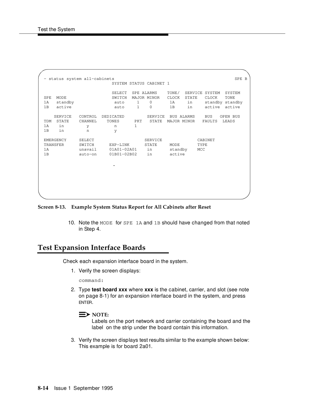
Screen
10.Note the MODE for SPE 1A and 1B should have changed from that noted in Step 4.
Test Expansion Interface Boards
Check each expansion interface board in the system.
1.Verify the screen displays: command:
2.Type test board xxx where xxx is the cabinet, carrier, and slot (see note
on page
ENTER.
![]()
![]() NOTE:
NOTE:
Labels on the port network and carrier containing the board and the label on the strip under the board contain this information.
3.Verify the screen displays test results similar to the example shown below: This example is for board 2a01.