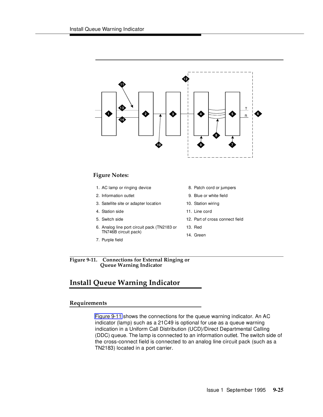
Install Queue Warning Indicator
12
11
1 3
1 | 2 | 3 |
14
10
|
| T |
4 | 5 | R |
|
|
8
97
6
Figure Notes:
1. | AC lamp or ringing device | 8. | Patch cord or jumpers |
2. | Information outlet | 9. | Blue or white field |
3. | Satellite site or adapter location | 10. | Station wiring |
4. | Station side | 11. | Line cord |
5. | Switch side | 12. | Part of cross connect field |
6. | Analog line port circuit pack (TN2183 or | 13. | Red |
| TN746B circuit pack) | 14. | Green |
|
| ||
7. | Purple field |
|
|