Processor Data Modules (PDMs) are connected to TN754B digital line circuit packs and are mounted individually or in a 71A data mounting. Other
The data mounting is connected by an A25D/B25A cable through the cross- connect field to a TN754B digital line circuit pack. The modules can also be mounted and connected individually through the
Installation
Connection to Data Mounting
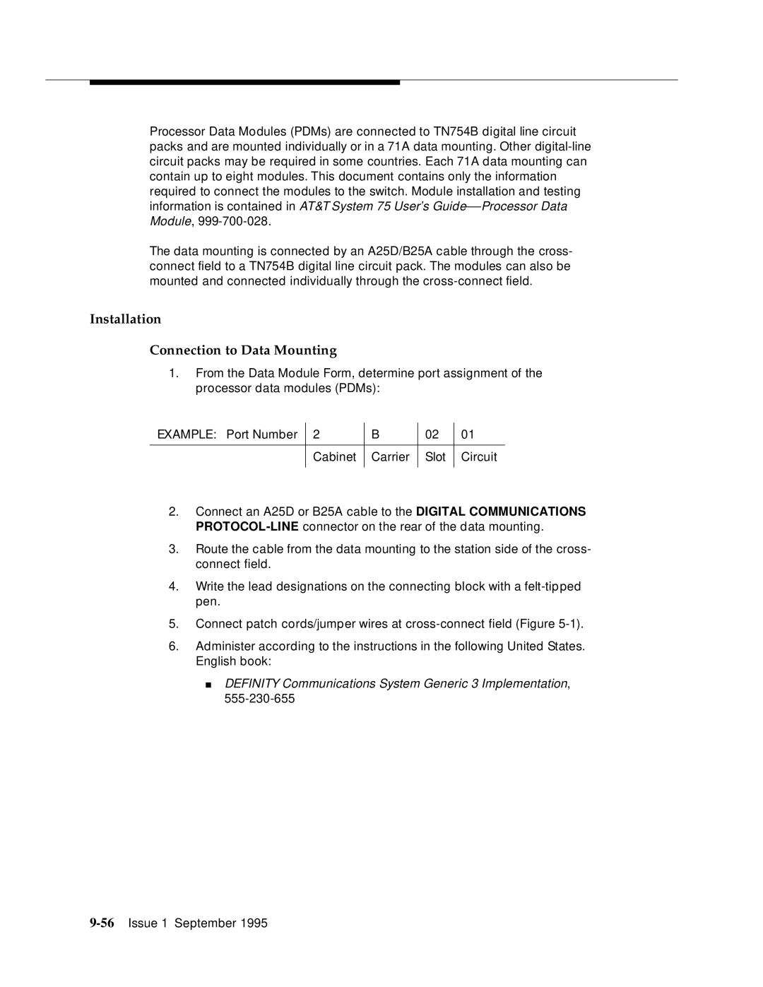
1.From the Data Module Form, determine port assignment of the processor data modules (PDMs):
EXAMPLE: Port Number | 2 | B | 02 | 01 |
|
|
|
|
|
| Cabinet | Carrier | Slot | Circuit |
|
|
|
|
|
2.Connect an A25D or B25A cable to the DIGITAL COMMUNICATIONS
3.Route the cable from the data mounting to the station side of the cross- connect field.
4.Write the lead designations on the connecting block with a
5.Connect patch cords/jumper wires at
6.Administer according to the instructions in the following United States. English book:
