Install Fibre-Optic Cables

1

2

1

TX

RX

2


6

5

3


2


TX


RX


1

4


Figure Notes:

1.Processor Port Network (PPN) Cabinet A Slot 2A01 / 9823-Type lightwave transceiver

2.FL2P-P-20 Fiber optic cable

3.Expansion Port Network (EPN) Cabinet A Slot 1A01 / 9823-Type lightwave transceiver

4.Fiber optic cable sheath, containing two fibers, each labeled 1 and 2, respectively

5.100A LIU

6.Cross connect field
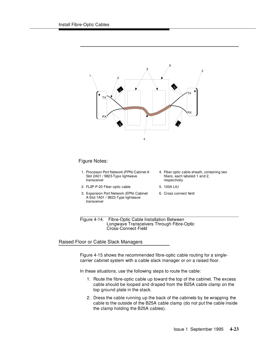
Figure 4-14. Fibre-Optic Cable Installation Between

Longwave Transceivers Through Fibre-Optic

Cross-Connect Field

Raised Floor or Cable Slack Managers

Figure 4-15shows the recommended fibre-optic cable routing for a single- carrier cabinet system with a cable slack manager or on a raised floor.

In these situations, use the following steps to route the cable:

1.Route the fibre-optic cable up toward the top of the cabinet. The excess cable should be looped and draped from the B25A cable clamp on the top ground plate in the stack.

2.Dress the cable running up the back of the cabinets by tie wrapping the cable to the outside of the B25A cable clamp (do not put the cable inside the clamp holding the B25A cables).

Issue 1 September 1995 4-23

Page 63
Image 63
AT&T 555-230-894 manual Raised Floor or Cable Slack Managers