Station Message Detail Recording (SMDR) Interface
Option Settings
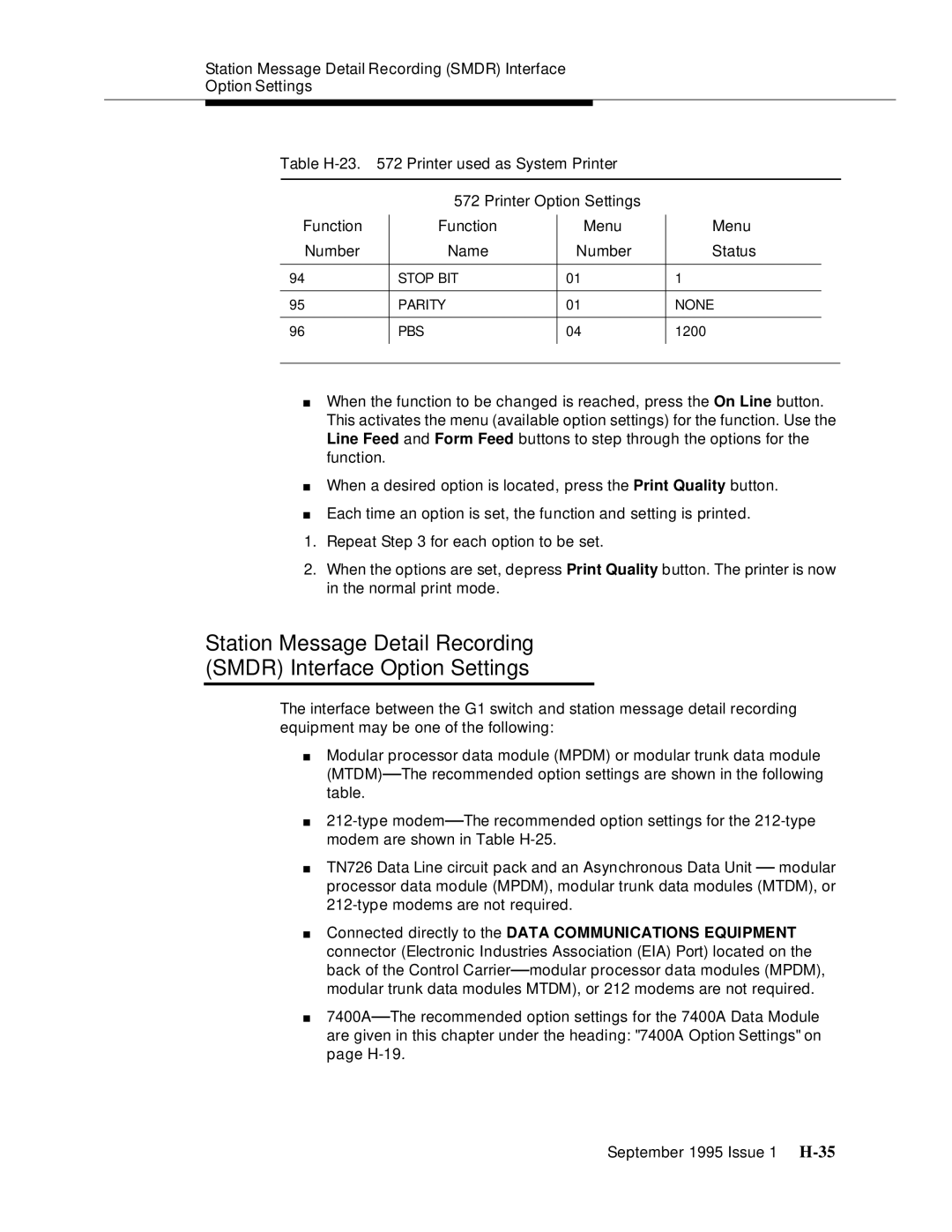
Table
| 572 Printer Option Settings |
|
| |
Function | Function | Menu | Menu | |
Number | Name | Number | Status | |
|
|
|
|
|
94 | STOP BIT | 01 | 1 |
|
|
|
|
|
|
95 | PARITY | 01 | NONE | |
|
|
|
|
|
96 | PBS | 04 | 1200 |
|
|
|
|
|
|
|
|
|
|
|
■When the function to be changed is reached, press the On Line button. This activates the menu (available option settings) for the function. Use the Line Feed and Form Feed buttons to step through the options for the function.
■When a desired option is located, press the Print Quality button.
■Each time an option is set, the function and setting is printed.
1.Repeat Step 3 for each option to be set.
2.When the options are set, depress Print Quality button. The printer is now in the normal print mode.
Station Message Detail Recording
(SMDR) Interface Option Settings
The interface between the G1 switch and station message detail recording equipment may be one of the following:
■Modular processor data module (MPDM) or modular trunk data module (MTDM)— The recommended option settings are shown in the following table.
■
■TN726 Data Line circuit pack and an Asynchronous Data Unit — modular processor data module (MPDM), modular trunk data modules (MTDM), or
■Connected directly to the DATA COMMUNICATIONS EQUIPMENT connector (Electronic Industries Association (EIA) Port) located on the back of the Control Carrier— modular processor data modules (MPDM), modular trunk data modules MTDM), or 212 modems are not required.
■7400A— The recommended option settings for the 7400A Data Module are given in this chapter under the heading: "7400A Option Settings" on page
September 1995 Issue 1