Install and Connect the Cabinets
!CAUTION:
Do not route
4 | 4 |
2
1
4 | 3 | |
4 | ||
|
4 |
|
| 4 | |
|
|
|
|
|
|
|
|
|
|
5 | 5 |
Figure Notes:
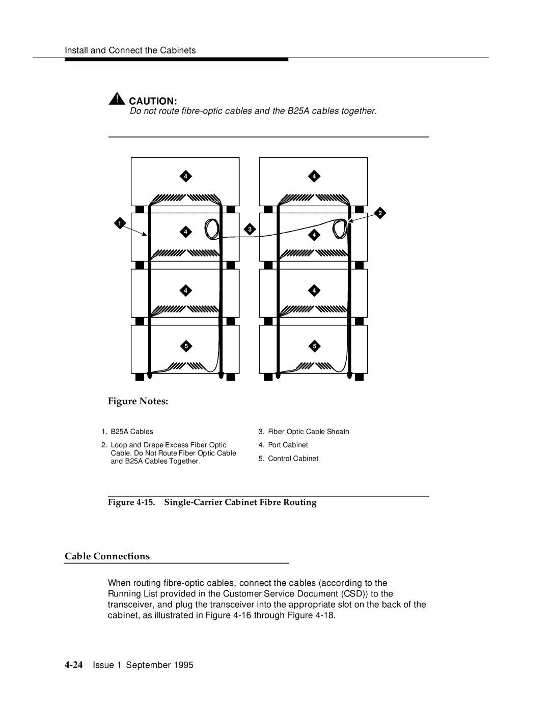
1. | B25A Cables | 3. | Fiber Optic Cable Sheath |
2. | Loop and Drape Excess Fiber Optic | 4. | Port Cabinet |
| Cable. Do Not Route Fiber Optic Cable | 5. | Control Cabinet |
| and B25A Cables Together. | ||
|
|
|
Figure 4-15. Single-Carrier Cabinet Fibre Routing
Cable Connections
When routing
