Install Auxiliary Equipment
| 1 |
|
| 2 |
|
| 3 |
|
| 4 | 2 |
|
| |
| 5 |
|
| 6 |
|
1 | 1 |
|
2 | 2 |
|
3 | 3 |
|
4 | 4 | 3 |
1 | 5 | |
5 |
| |
6 | 6 |
|
7 | 7 |
|
8 | 8 |
|
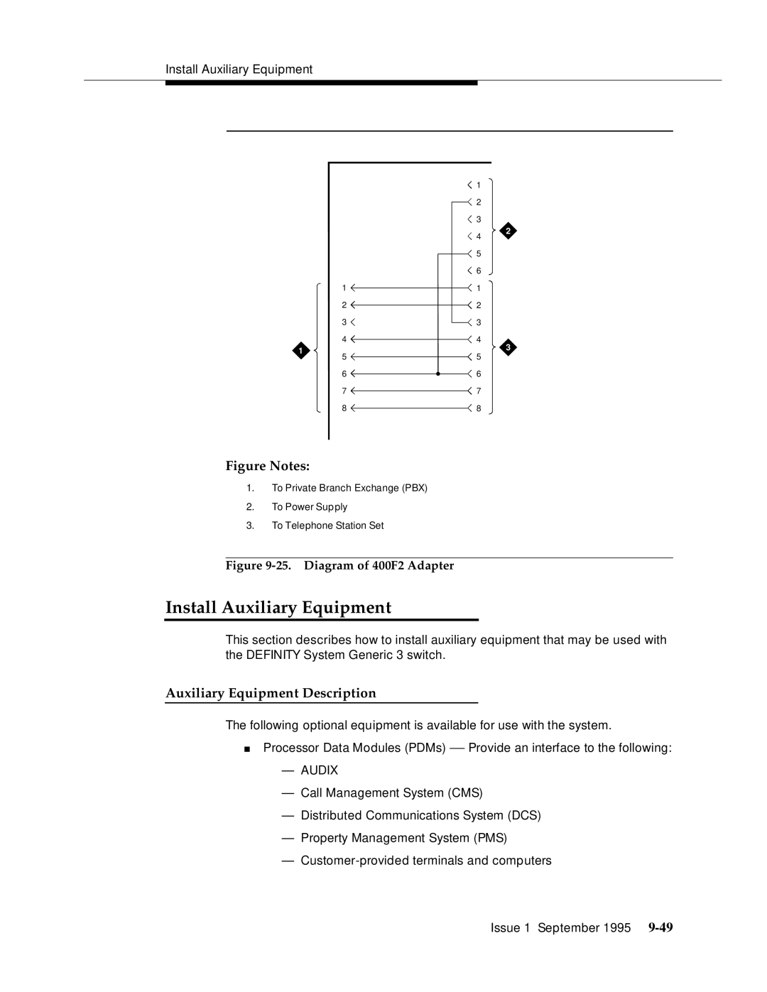
Figure Notes:
1.To Private Branch Exchange (PBX)
2.To Power Supply
3.To Telephone Station Set
Figure 9-25. Diagram of 400F2 Adapter
Install Auxiliary Equipment
This section describes how to install auxiliary equipment that may be used with the DEFINITY System Generic 3 switch.
Auxiliary Equipment Description
The following optional equipment is available for use with the system.
■Processor Data Modules (PDMs) — Provide an interface to the following:
—AUDIX
—Call M anagement System (CMS)
—Distributed Communications System (DCS)
—Property Man agement System (PMS)
—Custo
Issue 1 September 1995
