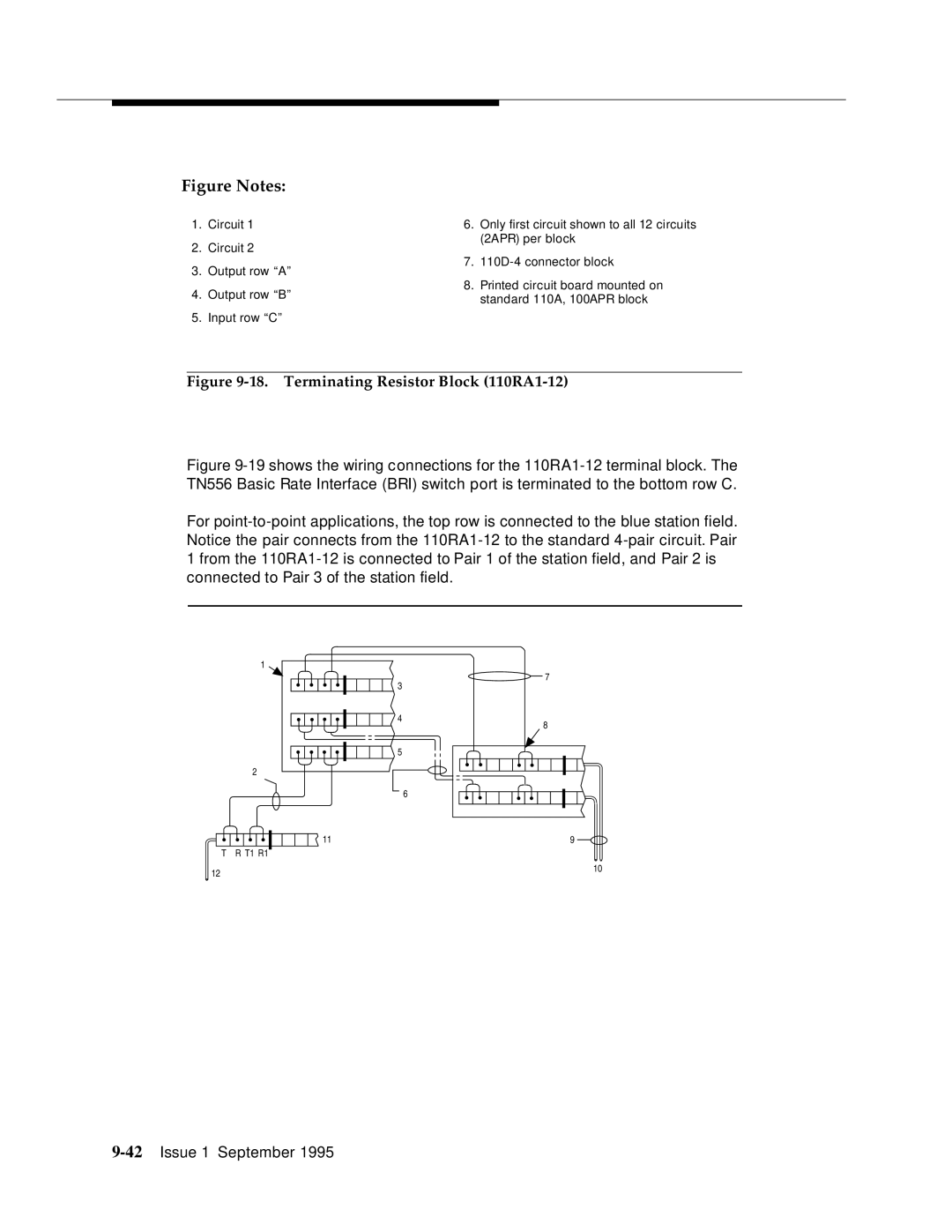
Figure Notes:
1.Circuit 1
2.Circuit 2
3.Output row “A”
4.Output row “B”
5.Input row “C”
6.Only first circuit shown to all 12 circuits (2APR) per block
7.
8.Printed circuit board mounted on standard 110A, 100APR block
Figure 9-18. Terminating Resistor Block (110RA1-12)
Figure 9-19 shows the wiring connections for the 110RA1-12 terminal block. The TN556 Basic Rate Interface (BRI) switch port is terminated to the bottom row C.
For point-to-point applications, the top row is connected to the blue station field. Notice the pair connects from the 110RA1-12 to the standard 4-pair circuit. Pair 1 from the 110RA1-12 is connected to Pair 1 of the station field, and Pair 2 is connected to Pair 3 of the station field.
1
2
3
4
5
7
8
T R T1 R1
12
![]() 11
11
6
9
10