201CR Modem Option Settings
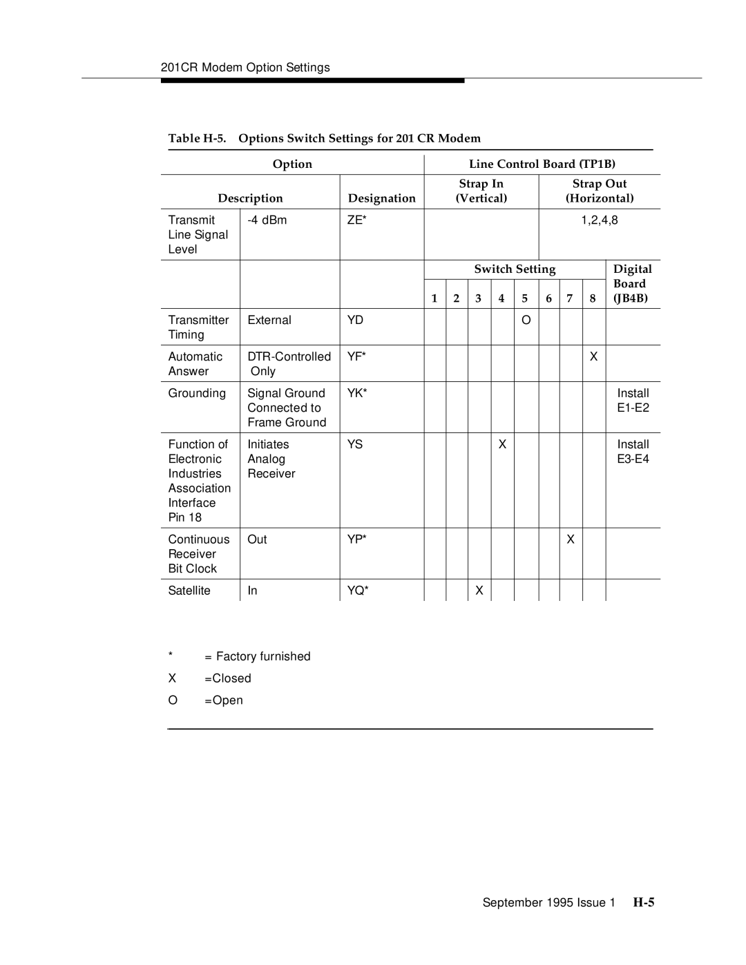
Table |
|
|
|
|
|
|
| |||||
| Option |
|
|
| Line Control Board (TP1B) | |||||||
|
|
|
| |||||||||
|
|
|
|
|
|
|
|
|
|
|
| |
|
|
|
| Strap In |
|
| Strap Out | |||||
Description | Designation |
| (Vertical) |
|
| (Horizontal) | ||||||
|
|
|
|
|
|
|
|
|
|
|
|
|
Transmit | ZE* |
|
|
|
|
|
|
| 1,2,4,8 | |||
Line Signal |
|
|
|
|
|
|
|
|
|
|
|
|
Level |
|
|
|
|
|
|
|
|
|
|
|
|
|
|
|
|
|
|
|
|
|
| |||
|
|
|
|
| Switch Setting |
|
|
| Digital | |||
|
|
|
|
|
|
|
|
|
|
|
| Board |
|
|
|
|
|
|
|
|
|
|
|
| |
|
|
| 1 | 2 | 3 | 4 | 5 | 6 | 7 |
| 8 | (JB4B) |
|
|
|
|
|
|
|
|
|
|
|
|
|
Transmitter | External | YD |
|
|
|
| O |
|
|
|
|
|
Timing |
|
|
|
|
|
|
|
|
|
|
|
|
|
|
|
|
|
|
|
|
|
|
|
|
|
Automatic | YF* |
|
|
|
|
|
|
|
| X |
| |
Answer | Only |
|
|
|
|
|
|
|
|
|
|
|
|
|
|
|
|
|
|
|
|
|
|
|
|
Grounding | Signal Ground | YK* |
|
|
|
|
|
|
|
|
| Install |
| Connected to |
|
|
|
|
|
|
|
|
|
| |
| Frame Ground |
|
|
|
|
|
|
|
|
|
|
|
|
|
|
|
|
|
|
|
|
|
|
|
|
Function of | Initiates | YS |
|
|
| X |
|
|
|
|
| Install |
Electronic | Analog |
|
|
|
|
|
|
|
|
|
| |
Industries | Receiver |
|
|
|
|
|
|
|
|
|
|
|
Association |
|
|
|
|
|
|
|
|
|
|
|
|
Interface |
|
|
|
|
|
|
|
|
|
|
|
|
Pin 18 |
|
|
|
|
|
|
|
|
|
|
|
|
|
|
|
|
|
|
|
|
|
|
|
|
|
Continuous | Out | YP* |
|
|
|
|
|
| X |
|
|
|
Receiver |
|
|
|
|
|
|
|
|
|
|
|
|
Bit Clock |
|
|
|
|
|
|
|
|
|
|
|
|
|
|
|
|
|
|
|
|
|
|
|
|
|
Satellite | In | YQ* |
|
| X |
|
|
|
|
|
|
|
|
|
|
|
|
|
|
|
|
|
|
|
|
*= Factory furnished
X=Closed
O =Open
September 1995 Issue 1