Install and Wire Telephones and Other Equipment
1 |
| 2 |
3 | 3 | 4 |
L O | L O | 4 8 |
L O * | L O * | 2 3 |
LI | L I | 2 2 |
L I* | L I* | 4 7 |
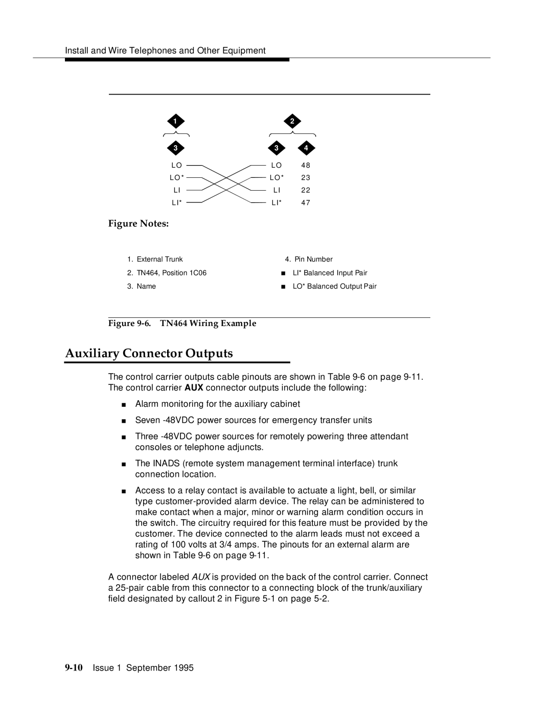
Figure Notes:
1. | External Trunk | 4. Pin Number | |
2. | TN464, Position 1C06 | ■ | LI* Balanced Input Pair |
3. | Name | ■ | LO* Balanced Output Pair |
Figure 9-6. TN464 Wiring Example
Auxiliary Connector Outputs
The control carrier outputs cable pinouts are shown in Table
■Alarm monitoring for the auxiliary cabinet
■Seven
■Three
■The INADS (remote system management terminal interface) trunk connection location.
■Access to a relay contact is available to actuate a light, bell, or similar type
A connector labeled AUX is provided on the back of the control carrier. Connect a
