Test the System
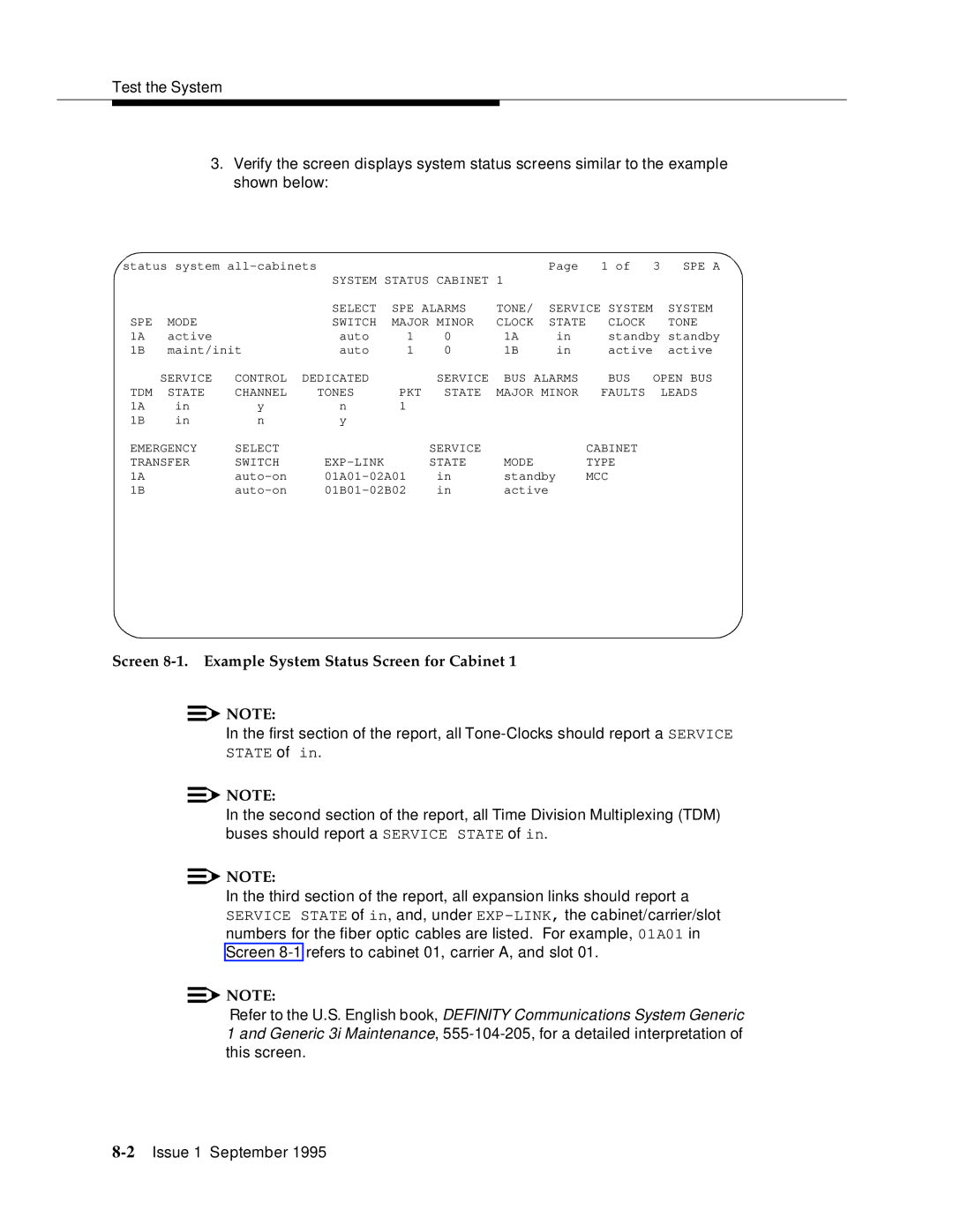
3.Verify the screen displays system status screens similar to the example shown below:
status system |
|
|
| Page | 1 of | 3 | SPE A | |||
|
|
| SYSTEM STATUS | CABINET | 1 |
|
|
|
| |
|
|
| SELECT | SPE ALARMS | TONE/ | SERVICE SYSTEM |
| SYSTEM | ||
SPE | MODE |
| SWITCH | MAJOR | MINOR | CLOCK | STATE | CLOCK |
| TONE |
1A | active |
| auto | 1 | 0 | 1A | in | standby standby | ||
1B | maint/init | auto | 1 | 0 | 1B | in | active |
| active | |
| SERVICE | CONTROL | DEDICATED |
| SERVICE | BUS ALARMS | BUS | OPEN BUS | ||
TDM | STATE | CHANNEL | TONES | PKT | STATE | MAJOR MINOR | FAULTS |
| LEADS | |
1A | in | y | n | 1 |
|
|
|
|
|
|
1B | in | n | y |
|
|
|
|
|
|
|
EMERGENCY | SELECT |
|
| SERVICE |
|
| CABINET |
|
| |
TRANSFER | SWITCH |
| STATE | MODE |
| TYPE |
|
| ||
1A |
| in | standby | MCC |
|
| ||||
1B |
| in | active |
|
|
|
| |||
|
|
|
|
|
|
|
|
|
|
|
Screen 8-1. Example System Status Screen for Cabinet 1
![]()
![]() NOTE:
NOTE:
In the first section of the report, all
![]()
![]() NOTE:
NOTE:
In the second section of the report, all Time Division Multiplexing (TDM) buses should report a SERVICE STATE of in.
![]()
![]() NOTE:
NOTE:
In the third section of the report, all expansion links should report a SERVICE STATE of in, and, under
![]()
![]() NOTE:
NOTE:
Refer to the U.S. English book, DEFINITY Communications System Generic
1and Generic 3i Maintenance,