Earthquake Protection Procedures
1 |
|
| 2 |
3 | 4 |
| 5 |
| 6 |
| 7 |
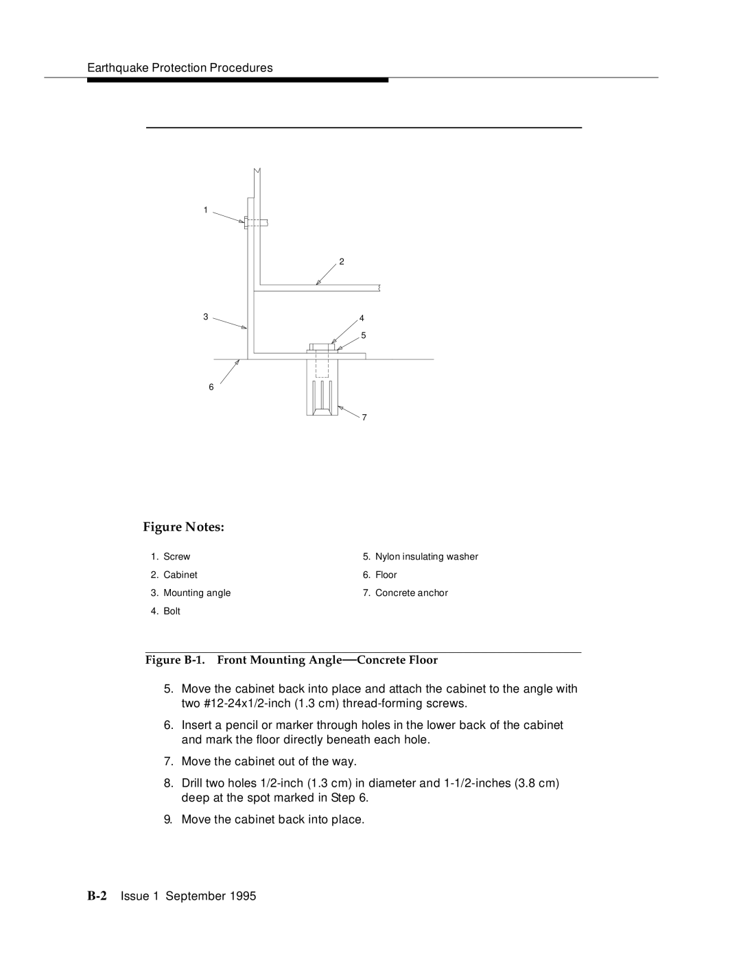
Figure Notes:
1. | Screw | 5. | Nylon insulating washer |
2. | Cabinet | 6. | Floor |
3. | Mounting angle | 7. | Concrete anchor |
4. | Bolt |
|
|
Figure B-1. Front Mounting Angle—Concrete Floor
5.Move the cabinet back into place and attach the cabinet to the angle with two
6.Insert a pencil or marker through holes in the lower back of the cabinet and mark the floor directly beneath each hole.
7.Move the cabinet out of the way.
8.Drill two holes
9.Move the cabinet back into place.