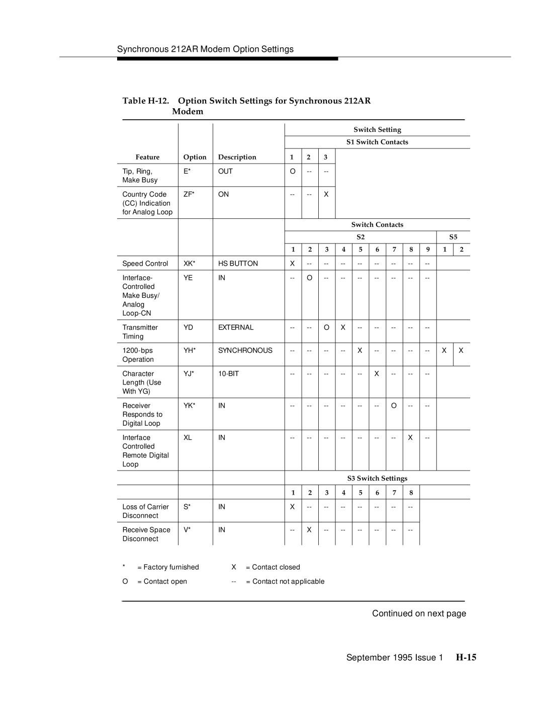
Synchronous 212AR Modem Option Settings
Table
Modem
Switch Setting
S1 Switch Contacts
Feature | Option | Description | 1 | 2 | 3 |
Tip, Ring, | E* | OUT | O | ||
Make Busy |
|
|
|
|
|
|
|
|
|
|
|
Country Code | ZF* | ON | X |
(CC)Indication for Analog Loop
|
|
|
|
|
|
|
|
| Switch Contacts |
|
|
|
|
| ||||
|
|
|
|
|
|
|
|
|
| S2 |
|
|
|
|
|
| S5 | |
|
|
|
|
|
|
|
|
|
|
|
|
|
|
|
|
|
|
|
|
|
|
|
| 1 | 2 | 3 | 4 |
| 5 | 6 | 7 |
| 8 | 9 | 1 |
| 2 |
|
|
|
|
|
|
|
|
|
|
|
|
|
|
|
|
| ||
Speed Control | XK* | HS BUTTON | X |
|
|
|
|
| ||||||||||
|
|
|
|
|
|
|
|
|
|
|
|
|
|
|
|
|
| |
Interface- | YE | IN |
| O |
|
|
|
|
| |||||||||
Controlled |
|
|
|
|
|
|
|
|
|
|
|
|
|
|
|
|
| |
Make Busy/ |
|
|
|
|
|
|
|
|
|
|
|
|
|
|
|
|
| |
Analog |
|
|
|
|
|
|
|
|
|
|
|
|
|
|
|
|
| |
|
|
|
|
|
|
|
|
|
|
|
|
|
|
|
|
| ||
|
|
|
|
|
|
|
|
|
|
|
|
|
|
|
|
| ||
Transmitter | YD | EXTERNAL | O | X |
|
|
|
|
| |||||||||
Timing |
|
|
|
|
|
|
|
|
|
|
|
|
|
|
|
|
| |
|
|
|
|
|
|
|
|
|
|
|
|
|
|
|
|
| ||
YH* | SYNCHRONOUS |
| X |
| X |
| X | |||||||||||
Operation |
|
|
|
|
|
|
|
|
|
|
|
|
|
|
|
|
| |
|
|
|
|
|
|
|
|
|
|
|
|
|
|
|
|
|
| |
Character | YJ* |
|
| X |
|
|
|
| ||||||||||
Length (Use |
|
|
|
|
|
|
|
|
|
|
|
|
|
|
|
|
| |
With YG) |
|
|
|
|
|
|
|
|
|
|
|
|
|
|
|
|
| |
|
|
|
|
|
|
|
|
|
|
|
|
|
|
|
|
|
| |
Receiver | YK* | IN |
|
| O |
|
|
|
| |||||||||
Responds to |
|
|
|
|
|
|
|
|
|
|
|
|
|
|
|
|
| |
Digital Loop |
|
|
|
|
|
|
|
|
|
|
|
|
|
|
|
|
| |
|
|
|
|
|
|
|
|
|
|
|
|
|
|
|
|
|
| |
Interface | XL | IN |
|
|
| X |
|
|
| |||||||||
Controlled |
|
|
|
|
|
|
|
|
|
|
|
|
|
|
|
|
| |
Remote Digital |
|
|
|
|
|
|
|
|
|
|
|
|
|
|
|
|
| |
Loop |
|
|
|
|
|
|
|
|
|
|
|
|
|
|
|
|
| |
|
|
|
|
|
|
|
|
|
|
|
|
|
|
|
|
|
|
|
|
|
|
|
|
|
|
|
| S3 Switch Settings |
|
|
|
|
| ||||
|
|
|
|
|
|
|
|
|
|
|
|
|
|
|
|
|
|
|
|
|
|
|
| 1 | 2 | 3 | 4 |
| 5 | 6 | 7 |
| 8 |
|
|
|
|
|
|
|
|
|
|
|
|
|
|
|
|
|
|
|
|
|
| |
Loss of Carrier | S* | IN |
| X |
|
|
|
|
|
| ||||||||
Disconnect |
|
|
|
|
|
|
|
|
|
|
|
|
|
|
|
|
| |
|
|
|
|
|
|
|
|
|
|
|
|
|
|
|
|
|
| |
Receive Space | V* | IN |
| X |
|
|
|
|
|
| ||||||||
Disconnect |
|
|
|
|
|
|
|
|
|
|
|
|
|
|
|
|
| |
* | = Factory furnished | X | = Contact closed |
|
|
|
|
|
|
|
|
|
|
|
|
| ||
O | = Contact open | = Contact not applicable |
|
|
|
|
|
|
|
|
|
|
| |||||
