Install and Connect the Cabinets
13 | ON | ON | ||
| ||||
|
|
|
|
|
| OFF | OFF | ||
2 | 3 |
|
|
|
| 7 | |||||
|
|
|
|
|
|
| |||||
|
|
| 4 |
|
|
| 6 |
|
| ||
|
|
|
|
|
|
|
|
| |||
1 |
|
| 1 |
|
|
| 5 |
|
|
|
|
ON ON | ON ON |
| ON ON | ||||||||
|
|
|
|
|
| 12 |
|
|
|
|
|
OFF |
|
| OFF OFF | OFF OFF | |||||||
12 | 11 | 7 |
|
77
9
8
10
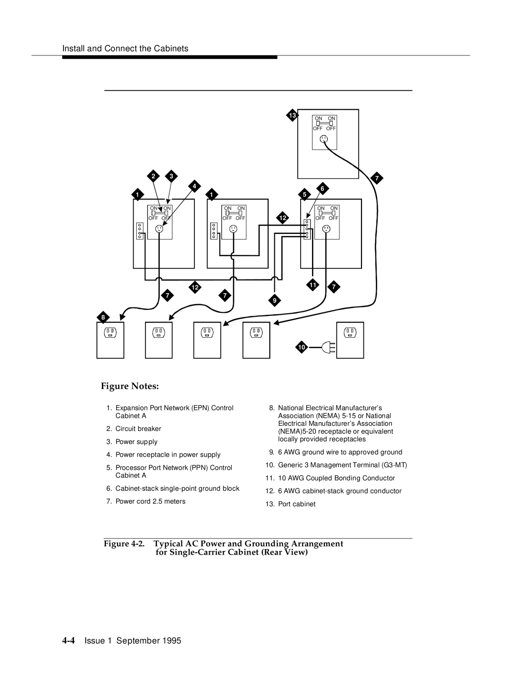
Figure Notes:
1.Expansion Port Network (EPN) Control Cabinet A
2.Circuit breaker
3.Power supply
4.Power receptacle in power supply
5.Processor Port Network (PPN) Control Cabinet A
6.
7.Power cord 2.5 meters
8.National Electrical Manufacturer’s Association (NEMA)
9.6 AWG ground wire to approved ground
10.Generic 3 Management Terminal
11.10 AWG Coupled Bonding Conductor
12.6 AWG
13.Port cabinet