Install Processor Data Modules (PDMs)
3
TXT
TXR
1 | PXT | 2 | |
PXR | |||
|
|
45
TXT
TXR
PXT 8
PXR
67
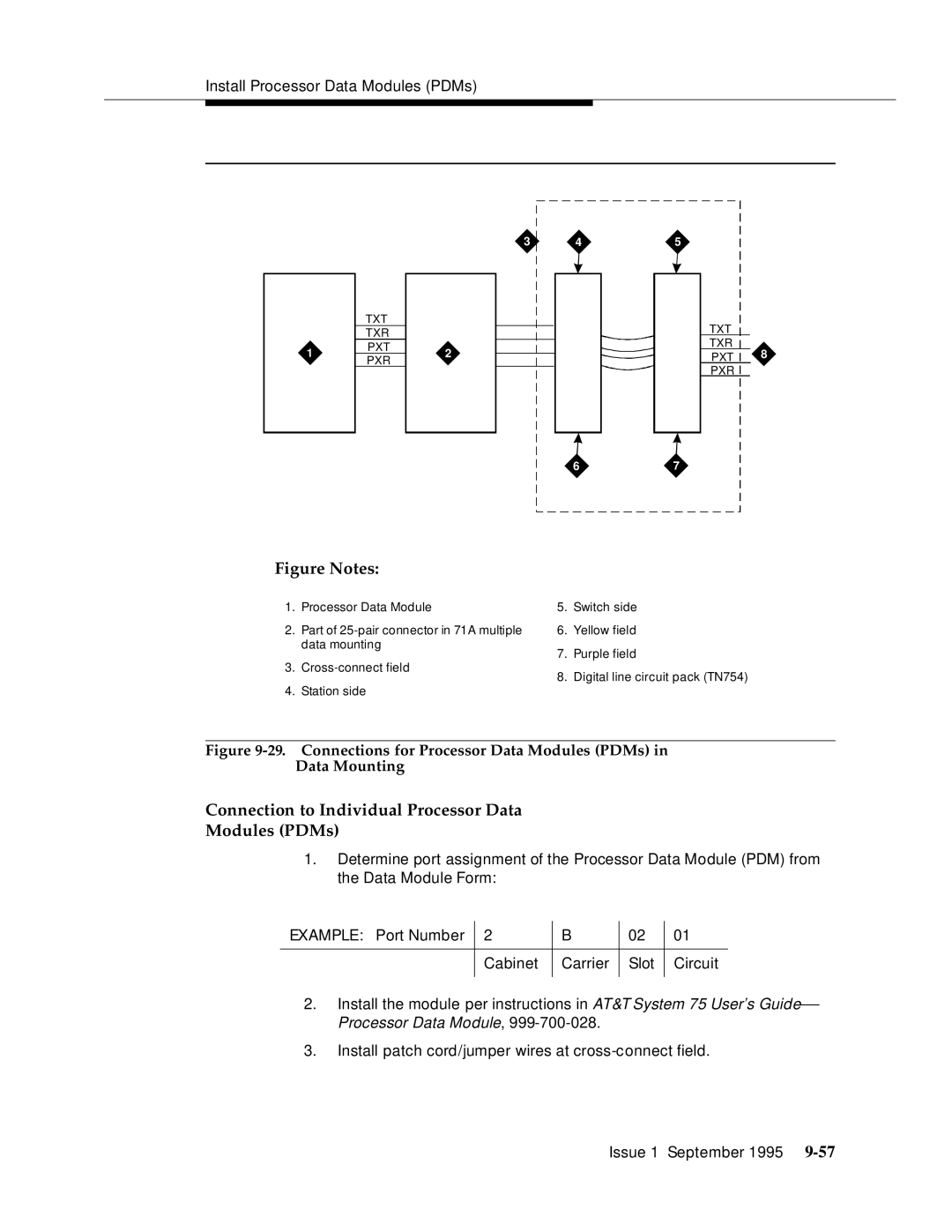
Figure Notes:
1.Processor Data Module
2.Part of
3.
4.Station side
5.Switch side
6.Yellow field
7.Purple field
8.Digital line circuit pack (TN754)
Figure 9-29. Connections for Processor Data Modules (PDMs) in Data Mounting
Connection to Individual Processor Data
Modules (PDMs)
1.Determine port assignment of the Processor Data Module (PDM) from the Data Module Form:
EXAMPLE: Port Number | 2 | B | 02 | 01 |
|
|
|
|
|
| Cabinet | Carrier | Slot | Circuit |
|
|
|
|
|
2.Install the module per instructions in AT&T System 75 User’s Guide— Processor Data Module,
3.Install patch cord/jumper wires at
Issue 1 September 1995