Install and Wire Telephones and Other Equipment
23
12
P+
13
P-
1
5
4 | 6 | 7 |
|
|
| 9 |
|
|
|
|
|
|
| |
8 | 10 | ||||
|
|
|
| ||
P+ | P+ |
| |||
|
|
|
| 13 | |
P- | P- |
| |||
|
|
|
|
|
|
TXT
TXR
PXT
PXR
11
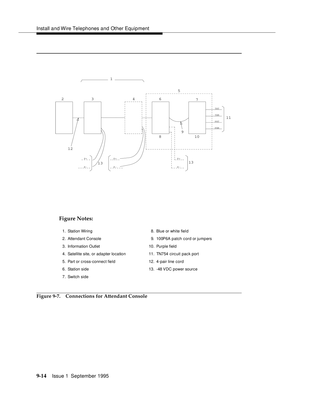
Figure Notes:
1. | Station Wiring | 8. | Blue or white field |
2. | Attendant Console | 9. | 100P6A patch cord or jumpers |
3. | Information Outlet | 10. | Purple field |
4. | Satellite site, or adapter location | 11. | TN754 circuit pack port |
5. | Part or | 12. | |
6. | Station side | 13. | |
7. | Switch side |
|
|