Install Property Management System (PMS) Interface
option switches is contained in the 3B2 Messaging Server Installation and Maintenance Service Manual,
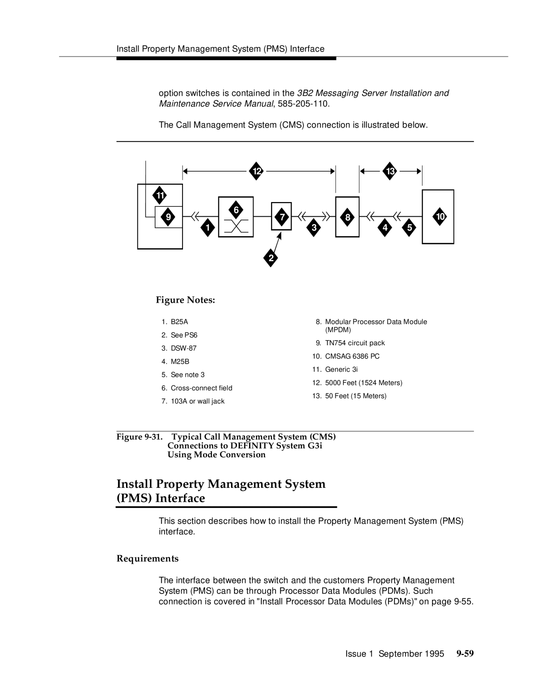
The Call Management System (CMS) connection is illustrated below.
|
|
|
|
| 12 |
|
|
|
|
|
|
|
|
|
| 13 |
|
|
| |||
|
|
|
|
|
|
|
|
|
|
|
|
|
|
|
|
|
|
|
|
|
|
|
11 |
|
|
|
|
|
|
|
|
|
|
|
|
|
|
|
|
|
|
|
|
|
|
|
|
|
|
|
|
|
|
|
|
|
|
|
|
|
|
|
|
|
|
|
| |
|
|
| 6 |
|
|
|
|
|
|
|
|
|
|
|
|
|
|
|
|
| 10 | |
9 |
|
|
|
|
|
|
|
|
|
|
|
|
|
|
|
|
|
|
|
| ||
|
|
|
|
|
| 7 |
|
|
|
|
| 8 |
|
|
|
|
|
|
| |||
|
|
|
|
|
|
|
|
|
|
|
|
|
|
|
|
|
|
| ||||
1 | 3 |
| 4 |
| 5 | |||||||||||||||||
|
|
|
|
|
|
|
|
|
|
|
|
| ||||||||||
|
|
|
|
|
|
|
|
|
|
|
| |||||||||||
|
|
|
|
|
|
|
|
|
|
|
|
|
|
|
|
|
|
|
|
|
|
|
|
|
|
| 2 |
|
|
|
|
|
|
|
|
|
|
|
|
|
| ||||
|
|
|
|
|
|
|
|
|
|
|
|
|
|
|
|
|
| |||||
|
|
|
|
|
|
|
|
|
|
|
|
|
|
|
|
|
| |||||
Figure Notes:
1. | B25A | 8. | Modular Processor Data Module | |
2. | See PS6 |
| (MPDM) | |
9. | TN754 circuit pack | |||
3. | ||||
|
| |||
4. | M25B | 10. | CMSAG 6386 PC | |
11. | Generic 3i | |||
5. | See note 3 | |||
|
| |||
6. | 12. | 5000 Feet (1524 Meters) | ||
13. | 50 Feet (15 Meters) | |||
7. | 103A or wall jack | |||
|
|
Figure 9-31. Typical Call Management System (CMS)
Connections to DEFINITY System G3i
Using Mode Conversion
Install Property Management System
(PMS) Interface
This section describes how to install the Property Management System (PMS) interface.
Requirements
The interface between the switch and the customers Property Management System (PMS) can be through Processor Data Modules (PDMs). Such connection is covered in "Install Processor Data Modules (PDMs)" on page
Issue 1 September 1995