DTE X.21
DTE X.21
Introduction
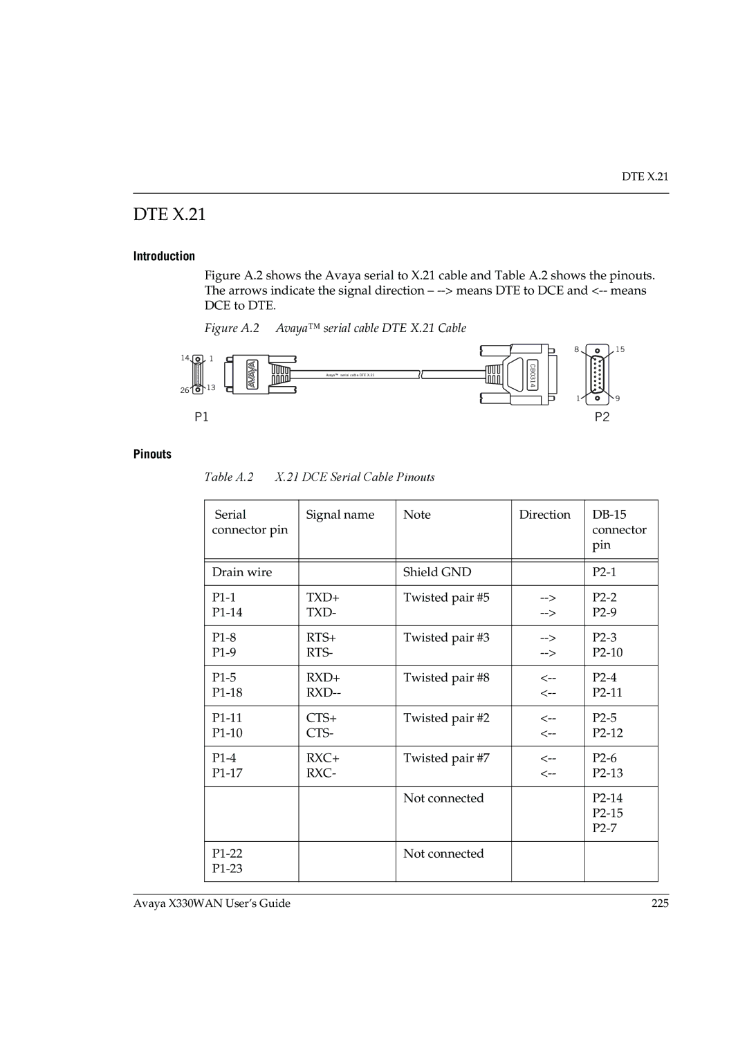
Figure A.2 shows the Avaya serial to X.21 cable and Table A.2 shows the pinouts. The arrows indicate the signal direction – --> means DTE to DCE and <-- means DCE to DTE.
Figure A.2 Avaya™ serial cable DTE X.21 Cable
14 ![]() 1
1
Avaya™ serial cable DTE X.21
26![]()
![]() 13
13
P1
Pinouts
Table A.2 X.21 DCE Serial Cable Pinouts
CB0314
8 | 15 |
1![]()
![]() 9
9
P2
| Serial | Signal name | Note | Direction |
| |
| connector pin |
|
|
| connector |
|
|
|
|
|
| pin |
|
|
|
|
|
|
|
|
|
|
|
|
|
|
|
| Drain wire |
| Shield GND |
|
| |
|
|
|
|
|
|
|
| TXD+ | Twisted pair #5 |
| |||
| TXD- |
|
| |||
|
|
|
|
|
|
|
| RTS+ | Twisted pair #3 |
| |||
| RTS- |
|
| |||
|
|
|
|
|
|
|
| RXD+ | Twisted pair #8 |
| |||
|
|
| ||||
|
|
|
|
|
|
|
| CTS+ | Twisted pair #2 |
| |||
| CTS- |
|
| |||
|
|
|
|
|
|
|
| RXC+ | Twisted pair #7 |
| |||
| RXC- |
|
| |||
|
|
|
|
|
|
|
|
|
| Not connected |
|
| |
|
|
|
|
|
| |
|
|
|
|
|
| |
|
|
|
|
|
|
|
|
| Not connected |
|
|
| |
|
|
|
|
|
| |
|
|
|
|
|
|
|
|
|
|
|
|
|
|
Avaya X330WAN User’s Guide | 225 |