Chapter 4 Operational Concepts and Configuration Examples
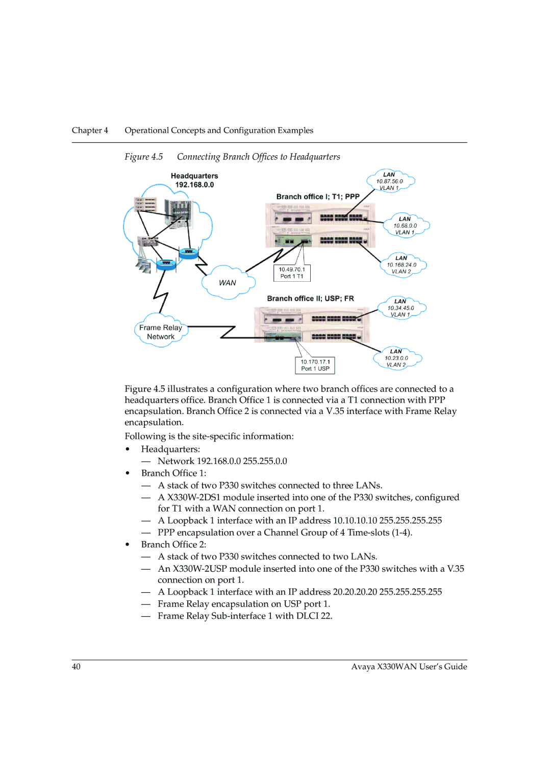
Figure 4.5 Connecting Branch Offices to Headquarters
Figure 4.5 illustrates a configuration where two branch offices are connected to a headquarters office. Branch Office 1 is connected via a T1 connection with PPP encapsulation. Branch Office 2 is connected via a V.35 interface with Frame Relay encapsulation.
Following is the site-specific information:
•Headquarters:
—Network 192.168.0.0 255.255.0.0
•Branch Office 1:
—A stack of two P330 switches connected to three LANs.
—A X330W-2DS1 module inserted into one of the P330 switches, configured for T1 with a WAN connection on port 1.
—A Loopback 1 interface with an IP address 10.10.10.10 255.255.255.255
—PPP encapsulation over a Channel Group of 4 Time-slots (1-4).
•Branch Office 2:
—A stack of two P330 switches connected to two LANs.
—An X330W-2USP module inserted into one of the P330 switches with a V.35 connection on port 1.
—A Loopback 1 interface with an IP address 20.20.20.20 255.255.255.255
—Frame Relay encapsulation on USP port 1.
—Frame Relay Sub-interface 1 with DLCI 22.
40 | Avaya X330WAN User’s Guide |
