Edacs CEC/IMC Manager
Page
Personal Computer Programming Software License Agreement
Iii
Credits
LBI-39224
This page intentionally blank
Contents
Distributed Multisite / Stargate Configuration
Console Configuration
Digital Voice Channel Configuration
Conventional Channel Configuration
Node Data
Feature Data
Diagnostics
Statistics
List of Figures
C3 Modular/Desktop Console Configuration Dialog Box 127
List of Tables
Xii
Welcome
About Your CEC/IMC Manager Operations Guide
Conventions
Xiv
Save
Option a Option B Option C
Xvi
About CEC/IMC Manager
About this Manual
CEC/IMC Manager Configuration
System Configuration
CEC/IMC Configuration
System Options
System Monitoring
Console Configuration
Help
Data Logging Feature
This page intentionally blank
CEC/IMC Manager Requirements
Unpacking
Important Note
Making Backups
Diskette Handling
Single CEC/IMC Manager No LAN
Upgrade CEC/IMC Manager
Multiple Remote Clients
Multiple CEC/IMC Managers on LAN
Important Note
LBI-39224
LBI-39224
System HOOK-UP
This page intentionally blank
Default User Account
Starting the Program
CEC/IMC Manager Main Window and Menu Bar
Help
User Account Configuration
Exit Program
CEC/IMC Manager Configuration Menu
Set Up Accounts
CEC/IMC Manager Configuration User Menu
User Access Level
Add User
Add
User Password
Modify Accounts
Delete
Cancel
CEC/IMC Manager Font Selection
Font Selection Dialog Box
CEC/IMC Manager Configuration Dialog Box
PC COM Port Selection
System Manager-MOM Baud Rate
CEC/IMC Manager-MOM Baud Rate
Data Logging Of GSC Traffic
Line Diagnostic Functions
System Time and Date
System Options Menu
Current Time and Date
Source of CEC/IMC Manager Date and Time
System Manager Database Uploads
Output CEC/IMC Manager Time to CEC/IMC
Read Disk
LBI-39224
Request
Current Status
Pending/History Status
Request from SysMgr
Transfer From System Manager
Entity
Send to CEC/IMC
Transfer From CEC/IMC Manager
TDM BUS Configuration
Number of Slots Remaining
SITE-TYPE Interface Module Channel Configuration
LBI-39224
MIM Channel Configuration
MIM Site Selection
Configurable Sites
Configured/Active Sites
Configured/Active Sites Prefix Definitions
Modify
Audio Interface Type Selection
Audio Board option
Desired
Audio Board-Equipped MIM Channel Configuration
View Current CEC/IMC Channel Configuration
View Current CEC/IMC Manager Channel Configuration
CEC/IMC to Disk
Output Signal Level dBm
Input Signal Level dBm
Channel Selection
Secure Tone
Channel Signaling
Bus/Slot Equipped
Notch Filter
ALC
Site Channel Configuration dialog box Save
Save and Send MIM Audio Board Configurations
Save As
Site Channel Configuration List dialog box Send
Save As… Dialog Box
T1/E1 Interface Card-Equipped MIM Configuration
T1/E1 Digital Site Configuration
Networked Systems Considerations
LBI-39224
LBI-39224
Analog/modem mode Analog or Digital Voice using Modems
Analog or Digital Voice
Frame Format
Signaling Type
Line Code
Set Site Channel Disbursement
Select Slave Clock Mode
Line Length
View
T1/E1 Interface Card Auto-configuration
Set Defaults
T1/E1 Channel Assignment
Subrate Port Assignments for Analog/Modem Mode
Subrate Port Channel Assignment
T1/E1 Interface Card Auto-configuration dialog box Save
Save And Send MIM T1/E1 Configurations
Synchronous Subrate Port Packing Arrangement
T1/E1 Digital Site Configuration dialog box Save
NIM Channel Configuration
Multinode Configuration
NIM Site Channel Configuration List Dialog Box
NIM Site Selection
Add
Audio Board Equipped NIM Configuration
NIM Site Channel Configuration Dialog Box
CEC/IMC to Disk
Channel Equipped
Save and Send NIM Audio Board Configurations
Close
T1/E1 Equipped NIM Configuration
T1/E1 Digital Site Configuration
LBI-39224
Help
Frame Format
View
T1/E1 Interface Card Auto-configuration
Save And Send NIM T1/E1 Configurations
T1/E1 Digital Site Configuration dialog box Save
PIM Channel Configuration
PIM Site Selection
Add
Audio Board-Equipped PIM Configuration
CEC/IMC to Disk
For a PIM Channel Signaling should always be set to None
Save and Send PIM Audio Board Configurations
Site Channel Configuration dialog box Save
T1/E1 Interface Card-Equipped PIM Configuration
LBI-39224
T1/E1 Digital Site Configuration
LBI-39224
Help
Frame Format
View
T1/E1 Interface Card Auto-configuration
Save And Send PIM T1/E1 Configurations
T1/E1 Digital Site Configuration dialog box Save
Vmim Channel Configuration
Vmim Configuration Menu
Vmim Site Selection
Help
Add
Vmim Audio Board Channel Configuration
CEC/IMC to Disk
Output Signal Level dBm
Save and Send Vmim Configuration
Close
Ctim Channel Configuration
Ctim Site Selection
Add
Ctim Audio Board Channel Configuration
Audio Interface Type
Help
Channel Selection
Channel Signaling
ALC
Save and Send Ctim Configurations
Close
Confirmed Call
Auto Confirm Call Database Fix
101
Save and Send
Dvim Confirmed Call
102
Telephone Interconnect
Read CEC/IMC
Caller ID
Console Configuration
Multiple Jessica PBX Gateways
CIM Console Selection
CIM Channel Configuration
105
Configured/Active Consoles
Configurable Consoles
106
Console Channel Configuration
107
CIM Audio Board Channel Configuration
108
109
Save and Send CIM Channel Configurations
110
Console Channel Configuration dialog box Save
111
Console Channel Configuration List dialog box Send
Console User Profile Configuration
112
Unit ID LID and Console Alias
Console Profiles
Console
113
System Manager prior to
System Manager 6.0 and greater
System Manager
114
Console User Setup Profiles
Supervisor
Visual Indicators
Audio Indicators
Emergency Indicators
Save and Send Console User Profile Configurations
120
11.3 C3 Maestro Console Hardware Configuration
121
Save and Send C3 Maestro Console Hardware Configurations
Digital Console Pre-empt
Console Privilege Lists
123
Saidxxxx
124
Unselect All
Configure Privilege Lists
125
Select All
Save And Send Console Privilege Lists
126
Configure Communication Modules
11.5 C3 Modular/Desktop Console Configuration
127
Number of Unselect Speaker
Module Type
Module Display Type
128
Module Present
Save And Send C3 Modular/Desktop Console Configurations
129
View Patch/Simulselect
130
State
Type
Said
Gscid
Site Mask
Digital Voice Channel Configuration
Caller
Deactivate
Dvim Selection
133
Configured/Active Dvim
Configurable Dvim
134
Dvim Configuration
135
Dvim Channel Configuration Dialog Box
136
Group ID GID
Group Alias
137
Dedicated Channels
Save and Send Dvim Configurations
Dynamic Channels
Undedicate
Dvim Channel Configuration List dialog box Send
Dvim Channel Configuration dialog box Save
139
Digital Causeway Causeway Default to Digital
140
Distributed Multisite / Stargate Configuration
StarGate Configuration
Group Call Console Tracking
Options and Controller Configuration
142
Serial Control Link Baud Rate
Save and Send StarGate Configurations
Remote CEC Interface
143
NIM Link-Up Verification
144
Conventional Channel Configuration
StarGate Network Conventional Channels
Conventional Channel Allocation
146
147
Conventional Channel Programming
148
Conventional Channel Configuration Dialog Box
149
150
CEC/IMC Manager-Based System Manager Uploads
Remote Conventional Channel Logged Warnings
Conventional Channel Database
Conventional Privilege List
Local/Remote Conventional Channel Dispatch
Causeway Patch / Simulselect
152
Causeway Patch Operation
153
Causeway Simulselect Operation
154
High-Level Configuration
Conventional Channel Configuration
155
156
LID Logical ID
157
Channel Location
Switch Number
Channel Alias
158
Channel Range
Local Conventional Channel Configuration
Switch Site
Conventional Interface Number
VOX/COR
Coupling
160
None
Relay Function
161
Standby Site
Remote Control
Control Signaling
Tone
DC E&M PTT
DC DC/E&M PTT
Simulselect
Save and Send High-level Configurations
Patch
164
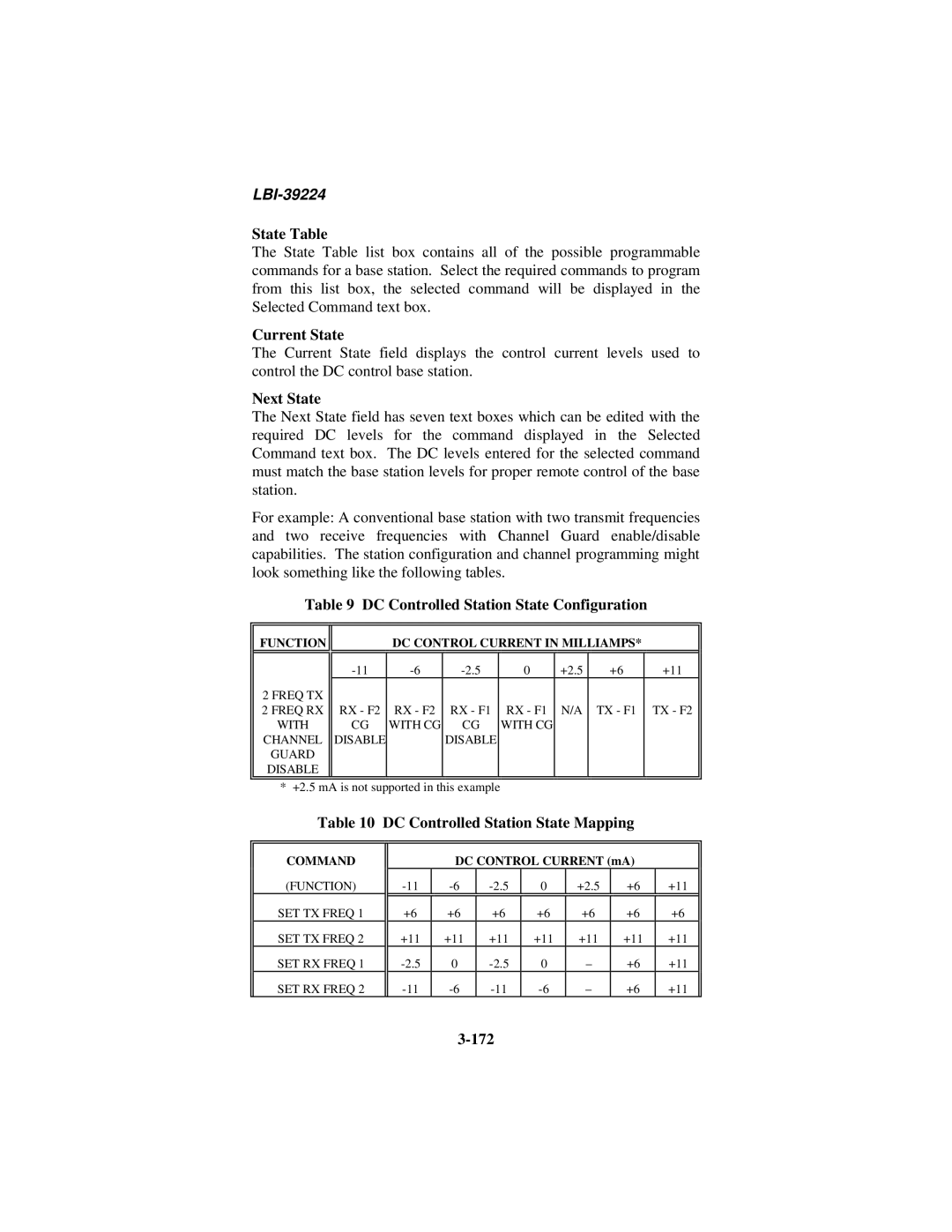
State Table
165
Command Definition
Tone Control/DC Control Configuration State Tables, Etc
Conventional Base Station Commands
166
Tone Controlled Station
State Table command
167
Tone Controlled Station State Table Mapping Dialog Box
168
Hz Hold Tone Level
Save and Send Tone Control Configurations
Command to Frequency Mapping
Delete Cmd
DC Controlled Station
170
DC Controlled Station State Mapping Dialog Box
171
Current State
DC Controlled Station State Configuration
State Table
Next State
Save and Send DC Control Configurations
173
Logging Recorder Configuration
Logging Recorder Configuration Dialog Box
Edit Mod
Lrim Module Configuration
Delete Mod
175
176
Save and Send Lrim Module Configurations
177
Send Mod
Edacs Data Gateway EDG Configuration
Program Lrim
Centralized Activity Logger CAL Configuration
Auxiliary I/O Configuration
18.1 I/O Event Configuration
180
Active State
Type Device and Assign Device
Bit
Event Type
Deactivate buttons
Console Tone Alarm
Input Event
Input Message
Output Event
Activate
Deactivate
Error/Warning Trigger
Error Trigger
Console Call Trigger
Log Event State Changes
Error/Warning Message Group and Error/Warning Msg Sub Group
Console Mask
185
Save and Send I/O Event Definitions
Default
Read and Delete I/O Event Definitions
186
Send All
Activate TDM BUS Slots
Save All
Multisite Unit Logout Configuration
Activate TDM Bus Slots
Unit/Group Location and Unit Logout Dialog Box
189
Timed Logout
190
Command Logout
191
Configure Unit Timed Logout
Unit Timed Logout Configuration
192
Manual Entry
Save/Send Timers
Set All Timers to Same
193
Command Unit Logout
Location Request
Unit Location
195
Group Location
Unit Location by Site
196
Multisite Settings
197
Multisite Monitor
Timer Master Enable/Disable
198
Redundant Clock
Wwvb Time Standard Configuration
Multisite Logout Polling
Redundant Clock Configuration
200
201
If Audio Boards Are Mixed
Recovery From Improper Redundant Clock Enabling
If Audio Boards Are Not Mixed
202
Prosound Configuration
ProSound Configuration
204
Local CEC/IMC ID read only
Site Alias read only
Priority System read/write
205
Control Channel read only
Save and Send ProSound Configurations
Adjacencies read only
206
Exiting the Program
208
System Monitoring
Node Data
CEC/IMC Diagnostics Node Matrix Screen
Node Matrix
Hot Buttons
Node Update
Current Errors
Hdlc B Stats
Board Identification
Current Node Data
Node ID
Errors
Board Identification Data
Assignment
Feature Data
Licensed Features
Licensed Capacities
Max Consoles
Licensed MSC Type
Max Sites
Max Network
Active Device Selection
Diagnostics
Max Net Chan
Diagnostic Options
Active Devices Dialog Box
Save To File
View Errors Current and Logged
Display
Print
LBI-39224
Diagnostics Dialog Box, Warnings Option Selected
View Warnings
Call Translation
Diagnostics Dialog Box, Call Translation Option Selected
Diagnostics Dialog Box, GSC Data Option Selected
GSC Data
Diagnostics Dialog Box, GSC Translation Option Selected
GSC Translation
Statistics
Hdlc Statistics
GSC ID
Clear Data
Last Cleared
Assign
Status
Errors Tx
Errors Rx
Frame
GSC Node Statistics
GSC Node Statistics Dialog Box
Dual Port Buffer Overflows
GSC Tx errors
GSC Rx errors
152 ⇒ 186 Overflows
NIM Statistics
NIM Statistics Dialog Box
Call Blocked
Call Statistics Chan Assign
Call Queued
Queue Statistics Avg Q Time
Link State
TEC T1/E1 Interface Card Status and Statistics
Clear Stats
Status Card Number
Device Type
Device Assign
Sig Active
Pos Fslips
Frmr Alarm
Statistics Card Number
Neg Fslips
CRC4 Alarm
Rem Alarms
Par Errors
Cards Active
This page intentionally blank
OFF-LINE Diagnostic Functions
CALLS.EXE
Egcv
CHN ASS
GCV
GVG
Avgttu
Avgtt
Avgmtu
CTI
GSCMON.EXE
Time Data
Gscmon /d12-30-92 /b091000 /e091100 /n
Chapter NETCLOCK/2 Interface Option
Overview
Netclock Installation
NETCLOCK/2 Configuration
Hardware Installation Notes
CMD Interconnections
Sec Remote Output Interconnections
NETCLOCK/2 T-CMD Interconnections
Software Installation Notes
Additional Considerations
Installation Verification
Logged Error Message Data
Appendix a Logged Error Definitions
Cause Corrective Action
Logged Cause Error Corrective Message Data Action
Bank
BUS Fail GSC BUS
Link Fail
1s. Corrective
Device Conflict
Encryption Fail License Data BAD
Product Licenses for Windows NT
Appendix B Logged Warning Definitions
Logged Message Data
Logged Cause Corrective Message Data Action
Audio SUM Count
Patch Simulselect
Mismatch Audio
Overflow MOM
Logged Logged Messagedata
CIC
Timeout Safety
Value in USE
Logged Message Data Cause Corrective Action
Conv Chan
Licensed Feature
Appendix C Snmp Agent and Proxy for CEC/IMC Optional
Extension Agent Installation
SOFTWARE\Ericsson\EDACS\CurrentVersion
\WINMOM\WIMCAGT.DLL
Appendix D Font Selectable Dialog Boxes
This page intentionally blank
Appendix E Popup Message BOX Definitions
LBI-39224
LBI-39224
LBI-39224
LBI-39224
LBI-39224
LBI-39224
This page intentionally blank
Audio Board
Bit error rate
Aegis
C3 Maestro
Causeway patch
Call Director patch
CAM
Causeway simulselect
CIM
CEC
CNI
Dpram
Ctim
Dvim
Edacs
Fifo
Hscx
Getc
Hdlc
IMC
MOM
Lrim
MIM
MOM PC
PCM
NIM
Novram
PIM
RIM
RSM
StarGate Controller
Site
Site assignment number
StarGate Manager
Vmim
Xltr
This page intentionally blank
Index
42,3-44,4-26
Lrim
MIM
35, 3-42,3-44,4-26
Vmim