4085-001
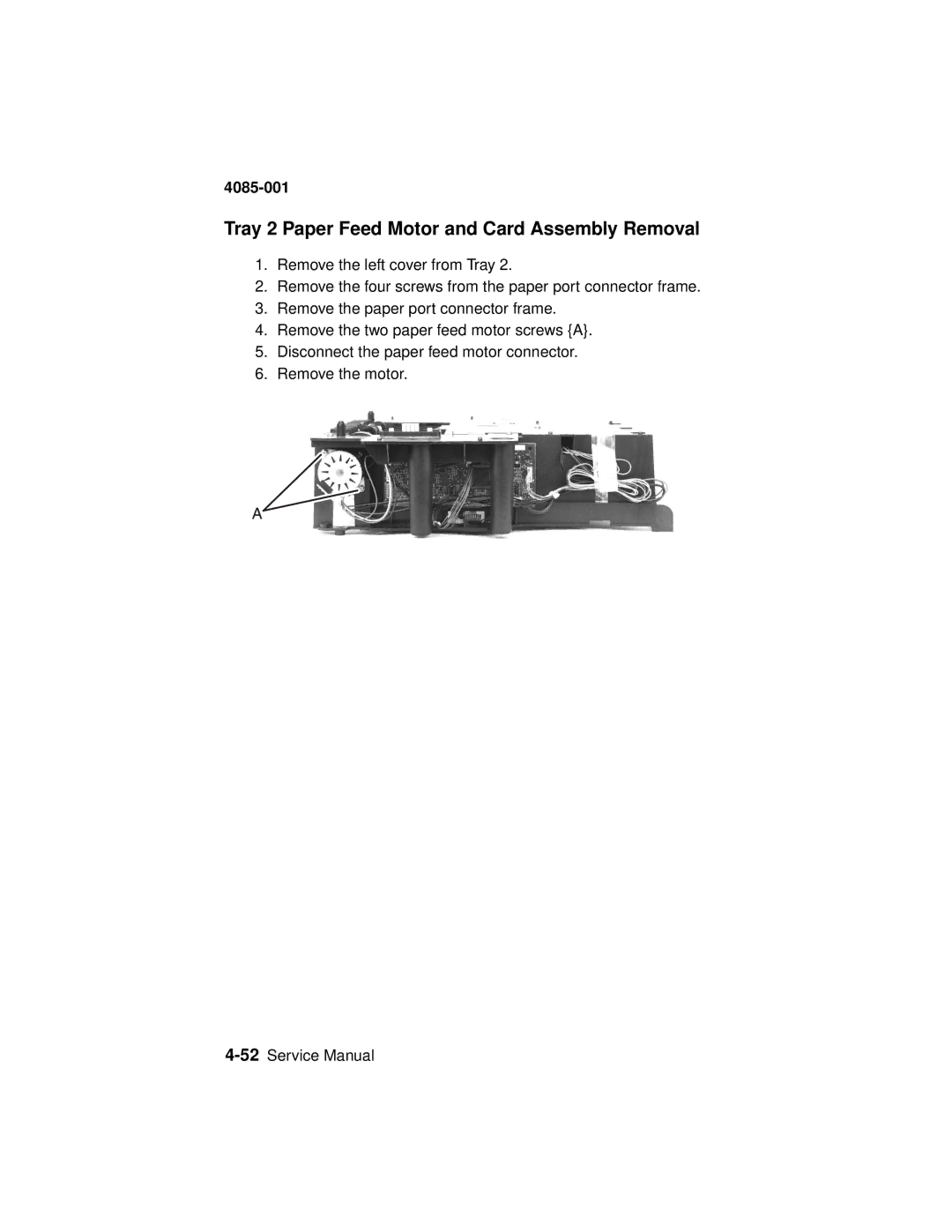
Tray 2 Paper Feed Motor and Card Assembly Removal
1.Remove the left cover from Tray 2.
2.Remove the four screws from the paper port connector frame.
3.Remove the paper port connector frame.
4.Remove the two paper feed motor screws {A}.
5.Disconnect the paper feed motor connector.
6.Remove the motor.