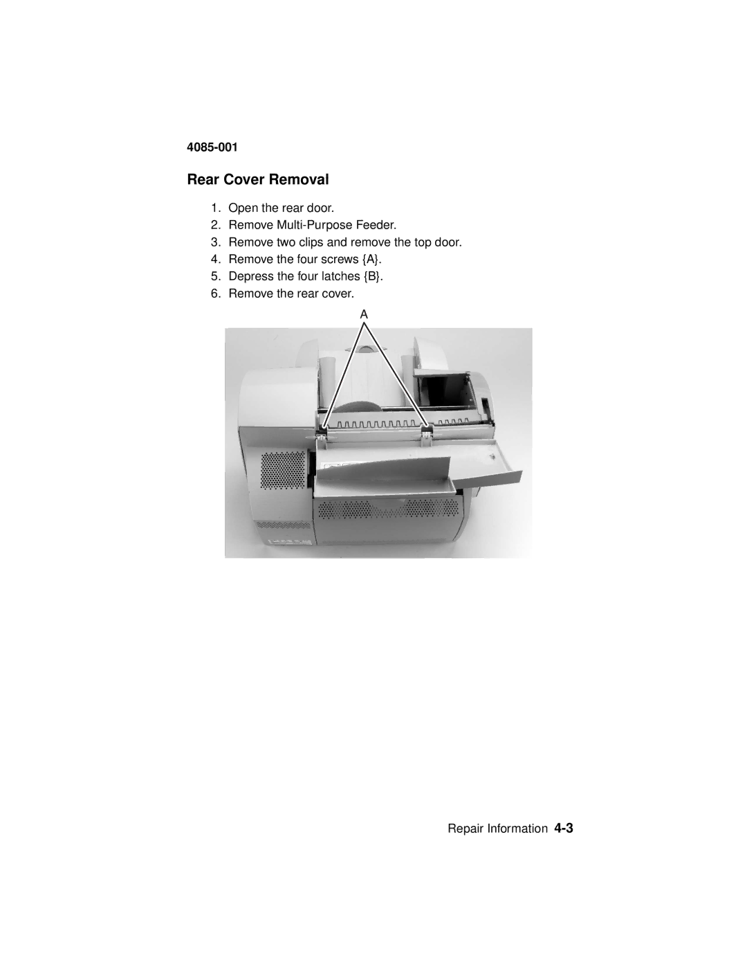
Manuals
/
Lexmark
/
Computer Equipment
/
Printer
Lexmark
Printer Rear Cover Removal, 4085-001, Open the rear door 2.Remove Multi-PurposeFeeder
Models:
J110
Printer
1
163
248
248
Download
248 pages
2.32 Kb
160
161
162
163
164
165
166
167
<
>
Specs
Install
Error codes
Maintenance
Configuration Menu Group
Post Symptom Table
Power-OnReset Button Functions
Diagnostic Information
Setup Menu
Index Card Assembly Removal
Page 163
Image 163
4085-001
Rear Cover Removal
1.
Open the rear door.
2.
Remove
Multi-Purpose
Feeder.
3.
Remove two clips and remove the top door.
4.
Remove the four screws {A}.
5.
Depress the four latches {B}.
6.
Remove the rear cover.
Repair Information
4-3
Page 162
Page 164
Page 163
Image 163
Page 162
Page 164
Contents
4085-001
•Table of Contents •Start Diagnostics
•Safety and Notices •Trademarks • Index
• Manuals Menu
UNITED STATES GOVERNMENT RESTRICTED RIGHTS
4085-001
U.S.A. P/N: 12G3639
Edition: August
4085-001
Table of Contents
ivService Manual
4085-00X
2-25
4085-001
4-26
4085-00X
4085-001
Preface
Consignes de Sécurité
Safety Information
4085-001
Sicherheitshinweise
Norme di sicurezza
4085-001
Informaçõ es de Seguranç a
Pautas de Seguridad
4085-001
4085-001
Informació de Seguretat
4085-001
xiiService Manual
1. General Information
Power Consumption
4085-001
4085-001
Internal Power Supply Specifications
Maintenance Approach
Outputs
Abbreviations
Tools Required For Service
4085-001
4085-001
Using the Operator Panel
Power Indicator States
Operator Panel and Menus
4085-001
Operator Panel Button Functions
General Information
4085-001
Printer Messages
4085-001
Operator Panel Menus
4085-001
Printing the Menu Settings Page
Utilities Menu
5.Press Select to select Print Menus
4085-001
Changing Printer Settings
4085-001
Disabling the Operator Panel Menus
Start
2. Diagnostic Information
4085-001
Jam Jog Function
Service Messages
4085-001
4085-001
Error Indicator Table
Error
Symptom
4085-001
2-4 Service Manual
Index System
4085-001
4085-001
2-6 Service Manual
Black Printhead
4085-001
4085-001
2-8 Service Manual
4085-001
RAM Memory Error - RAM
2-10 Service Manual
User Status Messages
4085-001
Action
4085-001
User Status Message
Status
4085-001
2-12 Service Manual
Diagnostic Information
Warning Messages
4085-001
2-14 Service Manual
Status Messages
4085-001
the Enabling
4085-001
Disabling/Enabling
the Disabling
4085-001
2-16 Service Manual
Action
4085-001
Status Message
Status
4085-001
2-18 Service Manual
Performing Self Test
4085-001
4085-001
2-20 Service Manual
Printing Alignment
4085-001
4085-001
2-22 Service Manual
Programming System
4085-001
4085-001
Attendance Messages
88 Cartridge Low
4085-001
4085-001
2-26 Service Manual
Change<input source>
4085-001
4085-001
Overriding Change Prompts
Check Tray
4085-001
4085-001
2-30 Service Manual
31 Defective
4085-001
4085-001
2-32 Service Manual
81 Engine Code
4085-001
4085-001
2-34 Service Manual
Load <input source>
4085-001
4085-001
2-36 Service Manual
Action
4085-001
Attendance Message
Description
4085-001
2-38 Service Manual
31 Missing
4085-001
203 Paper Jam Printer Input Sensor
Paper Jams
200 Paper Jam Printer Staging Sensor
201 Paper Jam Printer Input Roller Sensor
220 Paper Jam -Tray2
4085-001 204 Paper Jam Printer Staging Sensor
205 Paper Jam Printer Input Roller Sensor
209 Paper Jam Printer Input Roller Sensor
251 Paper Jam MPF
4085-001 250 Paper Jam MPF
Short Paper
4085-001 PerfectFinish Empty
Unsupported Printhead
Unsupported Ink Cartridge
4085-001
4085-001
Error Recovery from Attendance Conditions
Alarm
Error Recovery from Attendance Conditions
2-46 Service Manual
Error Type
Diagnostic Information
bExpect data loss when this condition occurs
4085-001
4085-001
Power-OnSelf Test POST Sequence
Action
Post Symptom Table
Symptom
4085-001
Maintenance Station Problems
Symptom Tables
Carrier Transport Problems
Communications Problems
Paper Feed Problems
4085-001 Operator Panel Problems
Power Problems
2-52 Service Manual
4085-001 Print Quality Problems
Maintenance Functions
Service Checks
4085-001
4085-001
2-54 Service Manual
4085-001
Maintenance Station Service Checks
Action
4085-001
Index Motor Service Check
Sensor Checks
2-56 Service Manual
4085-001
2-58 Service Manual
Operator Panel Buttons Service Check
4085-001
4085-001
Operator Panel LCD Display Service Check
Options Service Check
DRAM Memory Options
If you are experiencing a paper jam
Paper Feed Service Check
4085-001
4085-001
•A defective motor
•Defective power supply +62 V dc
2-62 Service Manual
4085-001
Dead Machine
Power Supply Service Check
4085-001
2-64 Service Manual
RIP Card Service Check
4085-001
4085-001
Print Quality Service Check
4085-001
2-66 Service Manual
Transport Service Check
Index Card/Sensor Service Check
4085-001
4085-001
2-68 Service Manual
Action
Cam System Motor/Sensor Service Check
User Error Messages
4085-001
4085-001
2-70 Service Manual
4085-001
54 Parallel Error
4085-001
2-72 Service Manual
4085-001
3. Diagnostic Aids
Power-OnReset Button Functions
Printer Operations
Entering CE Diagnostics Mode
4085-001 Disable/Enable Operator Panel Menus
Clear NVRAM non-criticalsections only
Enter Flash Engine Code Mode
4085-001
Change Printheads
Change Ink Cartridges
4085-001
4085-001
Aligning the Printheads
User Alignment
Coarse Alignment
4085-001
3-6 Service Manual
4085-001
Cleaning Printheads
Linking Input Trays
4085-001 Print Quality Test Page Fixed Settings
Input tray linking description
4085-001
4085-001
Printing Menu Settings Page
Unsolicited Manual Feed
Manual Duplex
4085-001
Menus Page Fixed Settings
Canceling a Print Job using the Operator Panel
Restoring Factory Defaults
4085-001 TSC fields on the Print Menus Page
4085-001
When a job is canceled
Invoking Cancel Job
Resetting the Printer using the Operator Panel
4085-001
4085-001
Diagnostic Aids
4085-001
Invoking Reset Printer from the Ready message
4085-001
Other Resets
Power On Reset --and similar resets
INIT * --Parallel Interface Initialization
4085-001 NPA Response
Printing Buffer Contents
Loss of Link Data and Link Response
4085-001
Activating Hex Trace Debug Mode
Diagnostics Mode 1 - Print Tests
Registration
Input Source Print Tests
Terminology
4085-001
<Input source> Printing
4085-001
LCD Hardware Test
Diagnostics Mode 2 - Hardware Tests
Contacts Page Fixed Settings
4085-001 Contacts Page Print Test
DRAM Memory Test
4085-001 Button Test
Terminology
4085-001
ROM Memory Test
Terminology
4085-001
Parallel Wrap Test
Terminology
4085-001
•Sync Busy Error •Byte Interrupt Request Error
4085-001
Diagnostics Mode 2 - Input Tray Tests
Tray 1 Sensor Test
Tray 2 Sensor Test
4085-001
MP Feeder Sensor Test
Terminology
4085-001
Diagnostics Mode 2 - Base Sensor Tests
Paper Path Sensors
Supplies Sensors
Miscellaneous Sensors
4085-001 Terminology
Terminology
Cap Printheads
Diagnostics Mode 2 - Subsystem Tests
4085-001 Ink Level Sensor Test
Uncap Printheads
4085-001
Carrier System Test
4085-001 Index System Test
Maintenance Sled Test
4085-001
Diagnostics Mode 2 - Supplies Tests
Ink Tank Memories
Printhead Memories
M&Y TSR Test
Diagnostics Mode 2 - Printer Setup
Setting the Page Count
4085-001 K&C TSR Test
Viewing the Permanent Page Count
Viewing and Resetting the Maintenance Page Count
4085-001
Viewing the Error Log
Diagnostics Mode 2 - Error Log
4085-001
4085-001
Clearing the Error Log
Menu List Display
4085-001 Exiting Diagnostics Mode
Menus
Understanding the Menu Display and Menu Buttons
4085-001
Printer Setting Display
4085-001 Printer Setting Value List Display
SUPPLIES MENU
4085-001
Print Quality =Normal
4085-001
Menu Groups
Operator Panel Menu Definition
4085-001
4085-001
Busy/Waiting Menu Group
Note: The Diagnostics Menu group should not
Diagnostic Aids
4085-001
Job Menu
Note: This operation is only
4085-001
SUPPLIES MENU
Ready Menu Group
4085-001
4085-001
Diagnostic Aids
Intermediate Menu, Setting, or Operation
or Setting
3-50 Service Manual
COLOR MENU
4085-001
FINISHING MENU
4085-001 PAPER MENU
4085-001
UTILITIES MENU
Operation
4085-001
Value
JOB MENU
SETUP MENU
4085-001
displayed if the printer’s operator panel ROM
Diagnostic Aids
4085-001
Note: Languages in this value list are only
saving the selected font as the default
Note: See “Symbol Set Display Format” on
page 3-58 for details on the Symbol Set
Size, Pitch, or Symbol Set has the affect of
4085-001
Font Name Display Format
PARALLEL MENU
4085-001 Symbol Set Display Format
Note: Only
Note: Only
USB MENU
4085-001
4085-001
Configuration Menu Group
4085-001
Note: Only displayed if Tray 2 is installed
Diagnostics Menu Group Mode 1: Printing
4085-001
4085-001
Diagnostics Menu Group Mode 2: Non-printing
4085-001
3-64 Service Manual
SUBSYSTEM TESTS
4085-001
4085-001
3-66 Service Manual
ERROR LOG
EXIT DIAGNOSTICS
Handling ESD-SensitiveParts
4. Repair Information
4085-001
4085-001
Adjustments
Removal Procedures
Releasing Plastic Latches
3.Remove two clips and remove the top door
Rear Cover Removal
4085-001
1.Open the rear door 2.Remove Multi-PurposeFeeder
4085-001
4-4 Service Manual
Exit Tray Removal
Operator Panel Cover/Operator Panel Removal
4085-001
1.Open the top door
Left Frame Cover Removal
4-6 Service Manual
4085-001
4085-001
Left Cover Removal
4085-001
4-8 Service Manual
4085-001
Right Cover/Power Switch Removal
4085-001
4-10 Service Manual
4085-001
Left Tray Cover Removal
4085-001
Right Tray Cover Removal
4.Remove the right cover
4085-001
4085-001
Engine Board /Cover Removal
4085-001
Carrier with Card Removal
4085-001
4-16 Service Manual
4085-001
Carrier 1st Stage Drive Belt Removal
Carrier Printhead Latch Removal
Multi-PurposeFeeder MPF Motor and Sensor Removal
4085-001
4-18 Service Manual
4085-001
Power Supply Removal
1.Remove all covers
4085-001
Repair Information
4085-001
4085-001
Index Card Assembly Removal
4085-001
Cover-OpenSensor Removal
4085-001
RIP-EMCShield Assembly/RIP Card Removal
Repair Information
4085-001
5.Remove two screws from the PerfectFinish sensor
4085-001
4085-001
Frame From Base Removal
4085-001
4-28 Service Manual
4085-001
Cam Engine Motor with Gear Removal
4085-001
4-30 Service Manual
1.Remove all covers
4085-001
4085-001
PerfectFinish Gear Plate Removal
PerfectFinish Motor Removal
Index Motor Assembly Removal
4085-001
4085-001
Encoder Disk Feed Roller Assembly Removal
Repair Information
4085-001
4085-001
Star Wheel Shaft Assembly Removal
Repair Information
4085-001
4085-001
Paper Feed Platen Assembly Removal
4085-001
Exit Shaft with Gear Removal
1.Remove all covers
4085-001
Repair Information
4085-001
4085-001
4-42 Service Manual
4085-001
Left Index Frame Pivot Assembly Removal
4085-001
4-44 Service Manual
4085-001
Right Index Frame Pivot Assembly Removal
2.Remove the spring between the cam followers
Bat Wings and Bushings Removal
4-46 Service Manual
4085-001
4085-001
Backup Roller Assembly Removal
Carrier/Cable Retainer Removal
Backup Roller Spring Removal
4085-001
Tray 2 Covers Removal
Peristaltic Pump Removal
4085-001
4085-001
Tray 2 Paper Pick Arm Assembly Removal
3.Remove E-clipB from pick assembly shaft
4-50 Service Manual
Repair Information
4085-001
4-52 Service Manual
Tray 2 Paper Feed Motor and Card Assembly Removal
3.Remove the paper port connector frame
5.Disconnect the paper feed motor connector
Engine Board
5. Connector Locations
4085-001
5-2 Service Manual
RIP Card
4085-001
Engine
RIP Card cont
Power Supply
4085-001
5-4 Service Manual
Optional Tray
4085-001
Carrier Transport System Pulleys
6. Preventive Maintenance
Lubrication Specifications
Carrier Shafts
4085-001
Carrier Card Pogo Pins
Motor Pulley Studs
Carrier Latch Camshaft Lubrication
7. Parts Catalog
How To Use The Parts Catalog
4085-001
7-2 Service Manual
Assembly 1: Covers
4085-001
Units
Assembly 1: Covers
4085-001
Part
7-4 Service Manual
Assembly 2: Paper Feed
4085-001
4085-001
Assembly 2: Paper Feed
7-6 Service Manual
Assembly 2 cont.: Paper Feed
4085-001
4085-001
Assembly 2 cont.: Paper Feed
7-8 Service Manual
Assembly 2 cont.: Paper Feed
4085-001
4085-001
Assembly 2 cont.: Paper Feed
12G6010
7-10 Service Manual
Assembly 3: Electronics
4085-001
4085-001
Assembly 3: Electronics
7-12 Service Manual
Assembly 3 cont.: Electronics
4085-001
4085-001
Assembly 3 cont.: Electronics
7-14 Service Manual
Assembly 3 cont.: Electronics
4085-001
4085-001
Assembly 3 cont.: Electronics
Parts Catalog
7-16 Service Manual
Assembly 4: Carrier Transport
4085-001
4085-001
Assembly 4: Carrier Transport
7-18 Service Manual
Assembly 5: Maintenance Station
4085-001
4085-001
Assembly 5: Maintenance Station
7-20 Service Manual
Assembly 6: Optional Tray
4085-001
4085-001
Assembly 6: Optional Tray
7-22 Service Manual
Assembly 7: Optional Multi-PurposeFeeder
4085-001
4085-001
Assembly 7: Optional Multi-PurposeFeeder
4085-001
7-24 Service Manual
12G6251
4085-001
12G6090
MarkNet External Print Server
4085-001
7-26 Service Manual
Index
4085-00X
X-2 Service Manual
4085-001
Part Numbers
4085-00X
X-4 Service Manual