Manuals
/
Lexmark
/
Computer Equipment
/
Printer
Lexmark
J110, Printer
manual
Assembly 3 cont. Electronics
Models:
J110
Printer
1
232
248
248
Download
248 pages
2.32 Kb
229
230
231
232
233
234
235
236
Page 232
Image 232
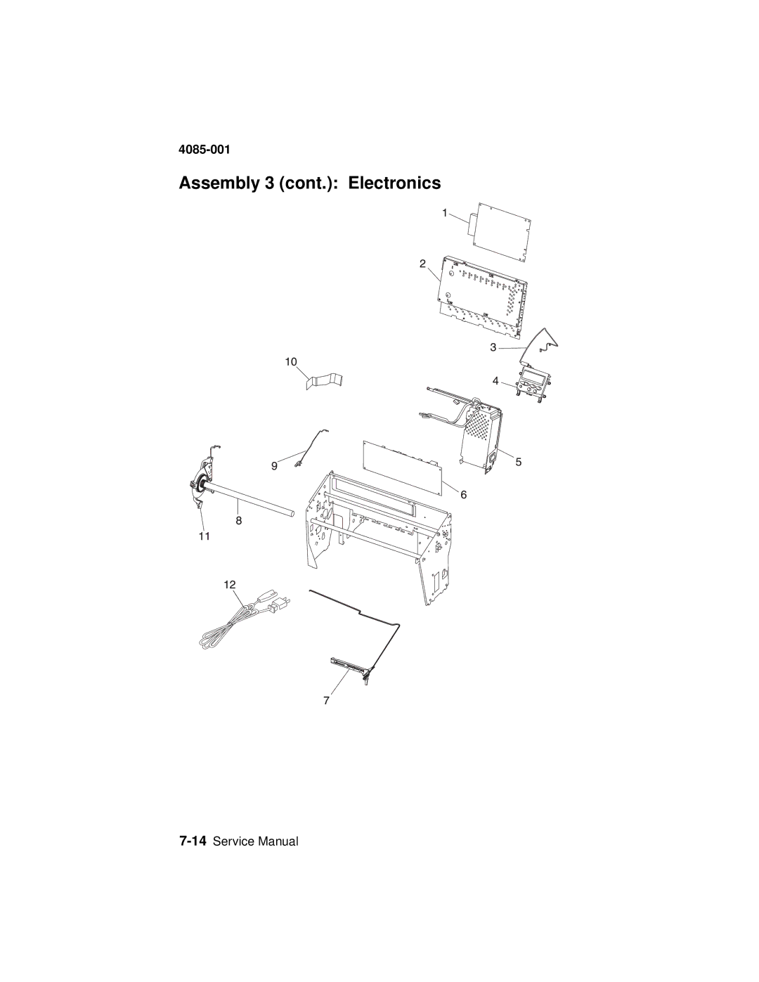
4085-001
Assembly 3 (cont.): Electronics
7-14
Service Manual
Page 231
Page 233
Page 232
Image 232
Page 231
Page 233
Contents
4085-001
4085-001
A. P/N 12G3639
Table of Contents
Diagnostic Aids
4085-00X
4085-001 Diagnostics Mode 2 Input Tray Tests
PerfectFinish Sensor Assembly/Rear Paper Path Sensor Removal
Preface
Safety Information
Consignes de Sécurité
Norme di sicurezza
Sicherheitshinweise
Pautas de Seguridad
Informaçõ es de Seguranç a
Informació de Seguretat
4085-001
Power Consumption
General Information
Internal Power Supply Specifications
Maintenance Approach
Outputs
Output Nominal Minimum Maximum Load Range Name Voltage
Tools Required For Service
Abbreviations
Power Indicator States
Using the Operator Panel
Operator Panel and Menus
Button Function
Operator Panel Button Functions
Menu
Printer Messages
Button Function Return
Operator Panel Menus
Utilities Menu
Printing the Menu Settings
Press Select to select Print Menus
Changing Printer Settings
Disabling the Operator Panel Menus
Diagnostic Information
Start
Accessing Additional Debug Information for Service Errors
Service Messages
Jam Jog Function
Error Indicator Table
Error Symptom Action
See Index Card Assembly
Index Card Assembly
Board. See Engine Board
System Test on
See Index Motor Service
Motor and Sensor Service
Diagnostics Mode on
Maintenance Sled Test
Change Printheads on
Carrier/Cable Retainer
Carrier. See Carrier/Cable
Retainer Removal on
Removal on page 4-48 . If
Engine Board /Cover
See Engine Board /Cover
4085-001
User Status Message Action
User Status Messages
Press Menu or Menu
Menu
To access the Busy
Panel Description Available on Status Message Screen
Status Message Action
Status Messages
Menu or Menu is
Disabling
Cancelling Job Appears after
Menu or Menu
All host links are
4085-001
4085-001
Printing Alignment Representation
FRU
4085-001
Attendance Messages
Attendance Message Description Action
Cartridge Low Representation Press Go to clear
4085-001
Press Menu or Menu
Overriding Change Prompts
4085-001
4085-001
4085-001
4085-001
4085-001
Once the error has
Plain Preprint
Requested manual source
To the Busy/Waiting
4085-001
Busy Waiting Menu
Paper Jams
Paper Jam Printer Staging Sensor
Paper Jam Printer Input Roller Sensor
Paper Jam Printer Input Sensor
4085-001 Paper Jam Printer Staging Sensor
Paper Jam Fail to make Input Roller Sensor PerfectFinish
Paper Jam Fail to make Staging Sensor Tray 2 PerfectFinish
Paper Jam -Tray
4085-001 Paper Jam MPF
4085-001 PerfectFinish Empty
Short Paper
Unsupported Ink Cartridge
Unsupported Printhead
4085-001 Error Recovery from Attendance Conditions
4085-001 Error Recovery from Attendance Conditions
4085-001
Power-On Self Test Post Sequence
Symptom Action
Post Symptom Table
Performing Self Test
Symptom Tables
Carrier Transport Problems
Communications Problems
Maintenance Station Problems
Paper Feed Problems
4085-001 Operator Panel Problems
Power Problems
4085-001 Print Quality Problems
See the Print Quality Service Check
Maintenance Functions
Service Checks
Function Description
4085-001
Replace sensor. See Maintenance Sled Test on
Maintenance Station Service Checks
Pump. See Peristaltic Pump Removal on
Index Motor Service Check
See the Index Motor Assembly Removal on
Sensor Checks
J16-1 and J16-2
Multi-Purpose Feeder MPF Motor and Sensor Service Check
Top view of the multi-purpose feeder connector pin numbers
Operator Panel Buttons Service Check
Operator Panel LCD Display Service Check
Options Service Check
Dram Memory Options
To check LCD, see LCD Hardware Test on
If you are experiencing a paper jam
Paper Feed Service Check
See Paper Jams on
Service Check on page 2-56 . If symptom
Service Check on page 2-63 . If the power supply
See Tray 1 Sensor Test on page 3-27 . If test
Check the position of tray 2 to insure that
Dead Machine
Power Supply Service Check
See Tray 2 Sensor Test on page 3-27 . If test
RIP Card Service Check
Print Quality Service Check
Align Printheads. See Aligning the Printheads on
Index Card/Sensor Service Check
Transport Service Check
Service Check on page 2-56 . If the index motor
Roller Assembly Removal on
See the Maintenance Station Service Checks on
User Error Messages
Cam System Motor/Sensor Service Check
Message Explanation
RAM
Data bits are set correctly on the printer
Service Check on
Power-On Reset Button Functions
Operations Initiated by Pressing Buttons at Power-On Reset
Printer Operations
4085-001 Disable/Enable Operator Panel Menus
Entering CE Diagnostics Mode
Enter Flash Engine Code Mode
Clear Nvram non-critical sections only
Change Ink Cartridges
Change Printheads
User Alignment
Aligning the Printheads
Coarse Alignment
Printer Setting Value Used for Menus
Cleaning Printheads
4085-001 Print Quality Test Page Fixed Settings
Linking Input Trays
Tray Letter Plain Paper Null Yes MP Feeder
Unsolicited Manual Feed
Printing Menu Settings
Manual Duplex
Menus Page Fixed Settings
Restoring Factory Defaults
Canceling a Print Job using the Operator Panel
4085-001 TSC fields on the Print Menus
Field Definition
4085-001
Resetting the Printer using the Operator Panel
Invoking Cancel Job
4085-001
4085-001 Invoking Reset Printer from the Ready message
Supplies Menu
Power On Reset -- and similar resets
Other Resets
Init * -- Parallel Interface Initialization
4085-001 NPA Response
Printing Buffer Contents
Loss of Link Data and Link Response
Diagnostics Mode 1 Print Tests
Activating Hex Trace Debug Mode
Registration
Terminology
Input Source Print Tests
4085-001
Diagnostics Mode 2 Hardware Tests
Contacts Page Fixed Settings
4085-001 Contacts Page Print Test
LCD Hardware Test
4085-001 Button Test
Dram Memory Test
ROM Memory Test
Parallel Wrap Test
4085-001
Tray 1 Sensor Test
Diagnostics Mode 2 Input Tray Tests
Tray 2 Sensor Test
MP Feeder Sensor Test
Paper Path Sensors
Diagnostics Mode 2 Base Sensor Tests
Supplies Sensors
4085-001 Terminology
Miscellaneous Sensors
Diagnostics Mode 2 Subsystem Tests
4085-001 Ink Level Sensor Test
Uncap Printheads
Cap Printheads
Carrier System Test
Maintenance Sled Test
4085-001 Index System Test
Ink Tank Memories
Diagnostics Mode 2 Supplies Tests
Printhead Memories
Setting the Page Count
Diagnostics Mode 2 Printer Setup
4085-001 TSR Test
Viewing and Resetting the Maintenance Page Count
Viewing the Permanent Page Count
Diagnostics Mode 2 Error Log
Viewing the Error Log
Clearing the Error Log
4085-001 Exiting Diagnostics Mode
Menus
Understanding the Menu Display and Menu Buttons
Menu List Display
Printer Setting Display
4085-001 Printer Setting Value List Display
Color Menu
Color
Menu Groups
Operator Panel Menu Definition
Waiting Menu Group on page 3-45 for a description
Busy/Waiting Menu Group
Top-Level Menu Intermediate Menus or Menu Items
SeeCanceling a Print Job using
Job Menu
Job Menu Operations Operation Value or Description
Operator Panel on
Contents on
Printer using the Operator Panel on
Ready Menu Group on
Top-Level Menu Intermediate Menu, Setting, or Operation
Ready Menu Group
Intermediate Menu Value Or Setting
Intermediate Menu or Setting Value
Color Menu
Paper Menu
Utilities Menu
Settings Page on
See Cleaning Printheads on
Operation Value
See Change Ink Cartridges on
See Restoring Factory Defaults on
Debug Mode on
Operation Value Reset Printer
Setting or Operation Value
Displayed if the printer’s operator panel ROM
PCL Emul Menu
Font Name Display Format
4085-001 Symbol Set Display Format
Setting Value
USB Menu
Configuration Menu Group
Intermediate Menu, Setting or Value Operation
Disable/Enable Operator Panel Menus
Operation see Clear Nvram non
See Aligning the Printheads on
Diagnostics Menu Group Mode 1 Printing
Registration
Diagnostics Menu Group Mode 2 Non-printing
See Exiting Diagnostics Mode on
See Contacts
Print Test on
See Tray 1 Sensor Test
See Tray 2 Sensor Test
See MP Feeder Sensor
See LCD Hardware
See Maintenance Sled
See Uncap Printheads
See Cap Printheads
See Carrier System
See Clearing the Error
See Viewing the Error
Log on
Repair Information
Handling ESD-Sensitive Parts
Removal Procedures
Adjustments
Releasing Plastic Latches
Rear Cover Removal
4085-001
Operator Panel Cover/Operator Panel Removal
Exit Tray Removal
Left Frame Cover Removal
Left Cover Removal
4085-001
Right Cover/Power Switch Removal
4085-001
Left Tray Cover Removal
Right Tray Cover Removal
Ink Levels and Temperature Sensor with Bracket Removal
Engine Board /Cover Removal
Carrier with Card Removal
4085-001
Carrier Printhead Latch Removal
Carrier 1st Stage Drive Belt Removal
Multi-Purpose Feeder MPF Motor and Sensor Removal
4085-001
Power Supply Removal
4085-001
4085-001
Index Card Assembly Removal
Cover-Open Sensor Removal
RIP-EMC Shield Assembly/RIP Card Removal
4085-001
PerfectFinish Sensor Assembly/Rear Paper Path Sensor Removal
Frame From Base Removal
Remove all covers. Refer to Rear Cover Removal on
4085-001
Cam Engine Motor with Gear Removal
4085-001
4085-001
PerfectFinish Gear Plate Removal
Index Motor Assembly Removal
PerfectFinish Motor Removal
Encoder Disk Feed Roller Assembly Removal
4085-001
Star Wheel Shaft Assembly Removal
4085-001
Paper Feed Platen Assembly Removal
Exit Shaft with Gear Removal
Paper Feed Frame and Motor/Cam Shaft Assembly Removal
4085-001
4085-001
Left Index Frame Pivot Assembly Removal
4085-001
Right Index Frame Pivot Assembly Removal
Bat Wings and Bushings Removal
Backup Roller Assembly Removal
Backup Roller Spring Removal
Carrier/Cable Retainer Removal
Peristaltic Pump Removal
Tray 2 Covers Removal
Tray 2 Paper Pick Arm Assembly Removal
4085-001
Tray 2 Paper Feed Motor and Card Assembly Removal
Connector Locations
Engine Board
RIP Card
USB
Optional Tray
Carrier Shafts
Lubrication Specifications
Carrier Transport System Pulleys
Motor Pulley Studs
Carrier Card Pogo Pins
Carrier Latch Camshaft Lubrication
How To Use The Parts Catalog
Parts Catalog
Assembly 1 Covers
Assembly 1 Covers
Asm Part Units Description Index Number
Assembly 2 Paper Feed
Assembly 2 Paper Feed
Assembly 2 cont. Paper Feed
Assembly 2 cont. Paper Feed
Assembly 2 cont. Paper Feed
Assembly 2 cont. Paper Feed
Assembly 3 Electronics
Assembly 3 Electronics
Assembly 3 cont. Electronics
Assembly 3 cont. Electronics
Assembly 3 cont. Electronics
Assembly 3 cont. Electronics
Assembly 4 Carrier Transport
Assembly 4 Carrier Transport
Assembly 5 Maintenance Station
Assembly 5 Maintenance Station
Assembly 6 Optional Tray
Assembly 6 Optional Tray
Assembly 7 Optional Multi-Purpose Feeder
Assembly 7 Optional Multi-Purpose Feeder
Assembly 8 Optional MarkNet External Print Server
Assembly 8 Optional MarkNet External Print Server
4085-001
Index
Flash Engine Code Mode
Part Numbers
7-9,7-13,7-17,7-19
Top
Page
Image
Contents