66 Installation and configuration
Procedure 4
Install the Ethernet Adapter card
1Remove the cover plate from the I/O panel at the rear of the IPE module.
2Remove the I/O panel retaining screws and lift the I/O panel from the module.
3Set up the I/O panel filter connector for the card slot you have assigned for the ICB card installation.
4Your next step depends on the configuration of that filter connector.
a If this connector has a permanent connection to the backplane cable, remove the filter connector from the I/O panel.
b If a
5Install the NT5D52AC Ethernet Adapter card into the selected I/O panel connector cutout using the saved retaining screws.
6Fasten the I/O panel to the module using the retaining screws.
7Replace the module cover plate.
This procedure is now complete
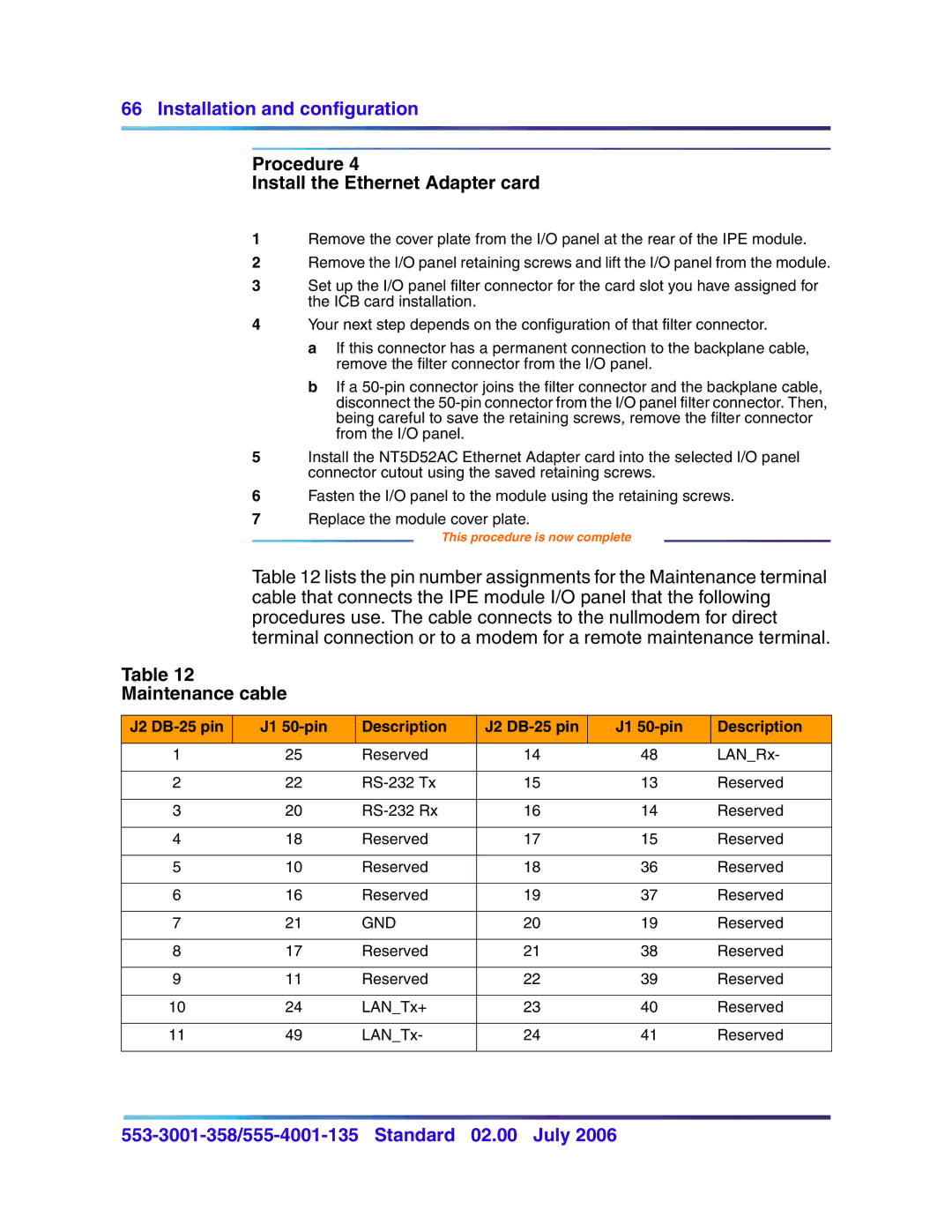
Table 12 lists the pin number assignments for the Maintenance terminal cable that connects the IPE module I/O panel that the following procedures use. The cable connects to the nullmodem for direct terminal connection or to a modem for a remote maintenance terminal.
Table 12
Maintenance cable
J2 | J1 | Description | J2 | J1 | Description |
|
|
|
|
|
|
1 | 25 | Reserved | 14 | 48 | LAN_Rx- |
|
|
|
|
|
|
2 | 22 | 15 | 13 | Reserved | |
|
|
|
|
|
|
3 | 20 | 16 | 14 | Reserved | |
|
|
|
|
|
|
4 | 18 | Reserved | 17 | 15 | Reserved |
|
|
|
|
|
|
5 | 10 | Reserved | 18 | 36 | Reserved |
|
|
|
|
|
|
6 | 16 | Reserved | 19 | 37 | Reserved |
|
|
|
|
|
|
7 | 21 | GND | 20 | 19 | Reserved |
|
|
|
|
|
|
8 | 17 | Reserved | 21 | 38 | Reserved |
|
|
|
|
|
|
9 | 11 | Reserved | 22 | 39 | Reserved |
|
|
|
|
|
|
10 | 24 | LAN_Tx+ | 23 | 40 | Reserved |
|
|
|
|
|
|
11 | 49 | LAN_Tx- | 24 | 41 | Reserved |
|
|
|
|
|
|