Installation and configuration 67
Table 12
Maintenance cable (Continued)
J2 | J1 | Description | J2 | J1 | Description |
|
|
|
|
|
|
12 | 12 | Reserved | 25 | N.C. | Not Connected |
|
|
|
|
|
|
13 | 23 | LAN_Rx+ |
|
|
|
|
|
|
|
|
|
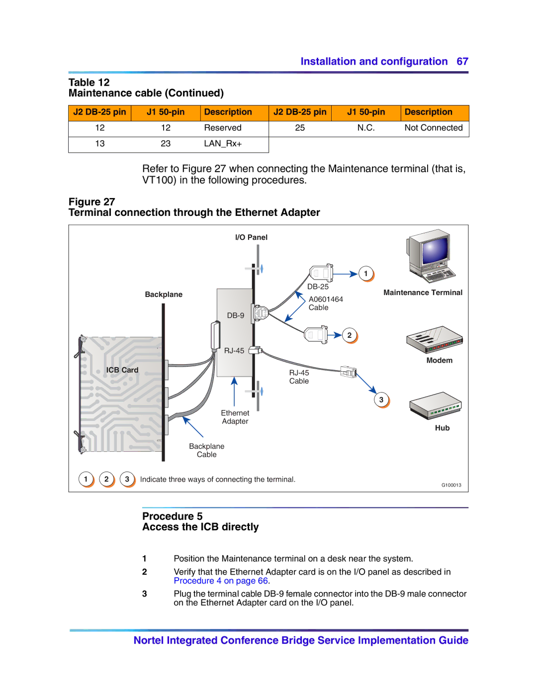
Refer to Figure 27 when connecting the Maintenance terminal (that is, VT100) in the following procedures.
Figure 27
Terminal connection through the Ethernet Adapter
|
|
|
| I/O Panel |
|
|
|
|
|
| 1 |
|
|
| Backplane | Maintenance Terminal | |
|
|
| A0601464 | ||
|
|
|
|
| |
|
|
|
| Cable |
|
|
|
|
|
| |
|
|
|
|
| 2 |
|
|
|
|
| |
|
|
|
|
| Modem |
| ICB Card |
|
| ||
|
|
|
|
| |
|
|
|
| Cable |
|
|
|
|
|
| 3 |
|
|
|
| Ethernet |
|
|
|
|
| Adapter | Hub |
|
|
|
|
| |
|
|
|
| Backplane |
|
|
|
|
| Cable |
|
1 | 2 | 3 Indicate three ways of connecting the terminal. | G100013 | ||
|
|
|
|
| |
Procedure 5
Access the ICB directly
1Position the Maintenance terminal on a desk near the system.
2Verify that the Ethernet Adapter card is on the I/O panel as described in Procedure 4 on page 66.
3Plug the terminal cable
Nortel Integrated Conference Bridge Service Implementation Guide
