Installation and configuration 69
In the procedures that follow, the connections are the same for the Option 11C and the CS 1000, the only difference is that the connectors are on the back of the Call Server and Media Gateway for the CS 1000, whereas they are on the bottom of the Option 11C cabinet.
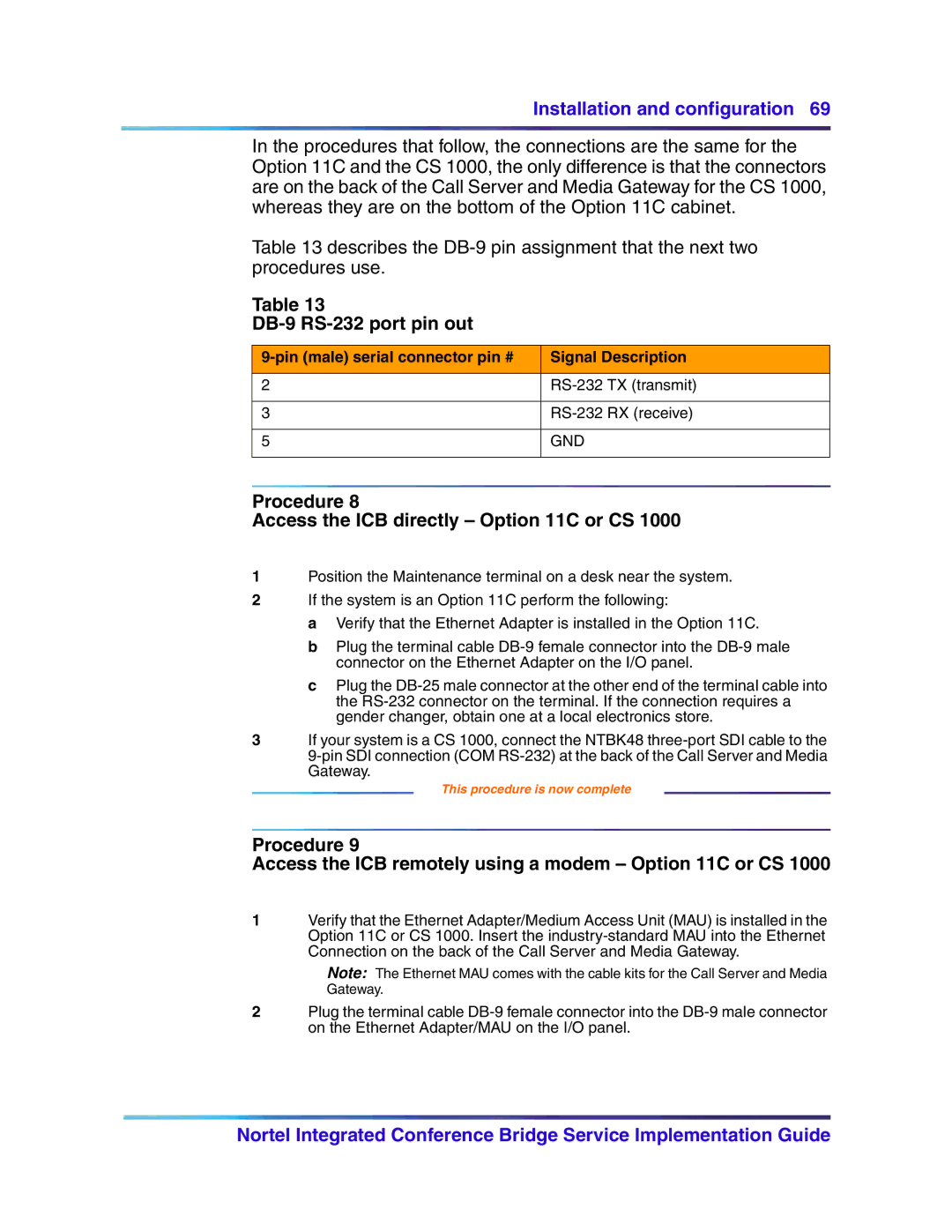
Table 13 describes the
Table 13
DB-9 RS-232 port pin out
| Signal Description | |
|
|
|
2 | TX (transmit) | |
|
|
|
3 | RX (receive) | |
|
|
|
5 | GND |
|
|
|
|
Procedure 8
Access the ICB directly – Option 11C or CS 1000
1Position the Maintenance terminal on a desk near the system.
2If the system is an Option 11C perform the following:
a Verify that the Ethernet Adapter is installed in the Option 11C.
b Plug the terminal cable
c Plug the
3If your system is a CS 1000, connect the NTBK48
This procedure is now complete
Procedure 9
Access the ICB remotely using a modem – Option 11C or CS 1000
1Verify that the Ethernet Adapter/Medium Access Unit (MAU) is installed in the Option 11C or CS 1000. Insert the
Note: The Ethernet MAU comes with the cable kits for the Call Server and Media Gateway.
2Plug the terminal cable
Nortel Integrated Conference Bridge Service Implementation Guide