Model No. KX-TVP200
Installation Manual
Installation Manual
Important Information
Model no Serial no
Trademarks
Precaution
For Your Safety Please Read the Following Text Carefully
Installation Manual
Table of Contents
Integrating the VPS with the Panasonic KX-TD Digital PBX
Final Setup
System Features
Glossary
Voice Processing System Overview
Basic Operations
Why Voice Processing?
What the VPS can and Cannot do
Time table Overflow function Disa message from a Disa card
VPS Limitations
VPS does not support
UCD functions
Subscriber Use
System Administration
System Management
Main Cabinet
System Basics
General
System Components
Ports 1-12 are at TNV
System Components
Hard Disk Drive
Mode Rotary Switch
Position Additional Function
CPU Board
Which Phone Systems are Compatible?
Hardware
Installer Equipment and Software Requirements
Specifications
Expansion Capabilities
Recommendations for System Configuration
PBX VPS
Inband/None Integration
Voice Mail Integration
Connection Examples
DPT Integration
Assigned as DPT VPS ports
Connection Example KX-TVP204
Do not connect the even-numbered jacks on the KX-TVP102 card
Connection Example KX-TVP102 3, DPT Integration Mode
Connection Example KX-TVP102 3, Inband/None Integration Mode
Voice Mail Integration
Installation
Installation
Safety Precautions
Wiring
Environmental Requirements
Unpacking
Mounting on a Concrete or Mortar Wall
Mounting the VPS on a Wall
Mounting on a Wooden Wall
Install the 3 screws included accessories into the rawlplugs
Frame Earth Connection
Installation Steps
Installation Steps
Expansion Capabilities of the VPS
Installing Port Expansion Cards KX-TVP102 or KX-TVP204
Installing the KX-TVP102 or KX-TVP204 Port Card
Port Expansion Cards
Anasonic
KX-TVP102 Card
KX-TVP204 Card
Modular Plug Connection
Connecting to the PBX
Connections
Opening the Ferrite Core
KX-TVP204 Not available KX-TVP102
Port Cards
Expansion Capabilities
Inband/None
Port Ports
Card Configuration Examples DPT Integration Pattern No
Total Number
Terminal Connection
Requirements for Connecting Programming Terminal
Connecting the RS-232C Cable
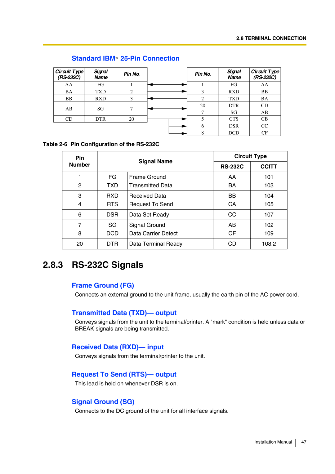
3 RS-232C Signals
Data Terminal Ready DTR- output
Integrating the VPS with Panasonic KX-T Phone Systems
How the VPS and the PBX Communicate
DPT or Inband Signalling?
Why Integration is Important
Guidelines for Integration
Message Waiting Notification from an SLT
Extension to extension Touchtone Signalling
PBX Requirements for Integration
Single Line Tip/Ring Port Circuits
Follow-on ID or Called Party ID
Screened Transfer from an SLT
General Guidelines and Definitions
PBX Parameters and Port Settings
2 RS-232C Settings
Port Settings
Alternate Extension Transfer Sequence
Integration Mode
Operator Transfer Sequence
Extension Transfer Sequence
Release Sequence for Call Waiting
Inband Signalling
Code Call State Sent to the Voice Mail Port When Default
Digit Translation Table Parameters
PBX Parameters and Port Settings
FTX FTX a
VPS Programming for Inband Integration
UK version KX-T1232 does not support Inband Integration
Recommended outside CO line feature settings
KX-TD500 Programming for Inband Integration
Assign Extension Group No. for the port
Set Card Status to INS
Screen output
Go to the 1-3 Extension Port Assignment screen
Assignment of the extension line to be connected to the VPS
Go to Recommended Settings
Recommended Settings
Assignment of Irna Intercept Routing No Answer destination
Assignment of Irna Intercept Routing No Answer timer
Screen output
Please Set First Ring Delay Timer to 5 s default 0 s
Assignment of Irna Intercept Routing No Answer timer
Screen output
System Data Programming Main Menu
Choose Station Setting from the Station Menu
Main Menu
Choose Station from the System Data Programming Main Menu
Choose Hunting Group Setting 1 from the Menu
Station Setting
DDI
CO Line Setting
Connecting the VPS with Panasonic KX-T Series PBXs
Connecting the VPS with Panasonic KX-T Series PBXs
Integrating the VPS with the Panasonic KX-TD Digital PBX
Guidelines for DPT Integration
Why DPT Integration is Important
DPT Integration Features
Set Status to INS
KX-TD500 Programming for Digital Integration
Go to the 1-1 Slot Assignment screen
Assignment of the ports to be connected to the VPS
Select TVP200-1 in the Type menu
Go to the 1-4 VPS DPT Port Assignment screen
Assign Extension Group No. for the port
Communication Parameters 9600, 8 Bit, None
System
Cause Remedy
Customising
Ascii Terminal
On Line MODE** is displayed
KX-TD500 Programming for Digital Integration
Enter
Software Verification
From the SYS-PGM no ? screen
= the port number you entered in programme 126 or
Enter 126 or
Press Store
Enter 127 or
Card Test System Setup
Installation
On Line MODE** is displayed
Sample display DB data PC Empty Version
Choose Voice Mail Integration from the System Menu
Choose System from the System Data Programming Main Menu
Voice Mail Integration
Installation Manual
Installation Manual
Live Call Screening LCS Programming
Common DPT Integration Features and Setup Procedures
Live Call Screening Password Assignment
Live Call Screening Password Cancelling
Conditions None
Enter the jack number. Screen output # Stop Rec
= the jack number you entered
Screen output Hands-Free or Private
Click Apply
To cancel the password, erase the 3-digit number
Live Call Screening Assignment via PC Programming
Hands-free
Dial 86 or
Screen output LCS Cancel
Dial 85 or 92. Screen output LCS Press Store
Dial 84 or
Dial 83 or
Screen output 2Way-Rec
= The extension number you entered
Button Assignment via PC Programming
Screen output
Click OK or Apply
Live Call Screening Password Control
Live Call Screening Activation
Example screen output
Restriction on TWR/TWT Activation
TWR Two-Way Recording into Mailbox
TWT Two-Way Transfer into Mailbox
Customising the System
Recording Messages
Quick Setup
Starting UP
Before Programming
PBX Type Press Enter
Starting the Quick Setup
PBX Type Required Procedures
Screen output
Extension Numbers for Mailboxes
Extension Numbers of VPS Ports Screen output
Creating Mailboxes
Example
Mailbox numbers displayed on this screen
Length of mailbox numbers
Password Setting Screen output
Port Service Setting Screen output
Activating the Quick Setup Screen output
Date and Time Setting Screen output
Screen output when Quick Setup is finished
Sample Custom Service Tree
Port Setting Options
Custom Service Setting Example
Sample Custom Service Message
Intercom Paging
Custom Service Features
Sample Custom Service for Foreign Languages
Time Service
Disconnect Parameter
Custom Service Programming
RS-232C Settings
Port Setting
System
None
Keypad Assignment Options Entry Function
Description Value Range Description/Function Default
Extn
Others None
Message Manager’s mailbox might be 98, 998, 9998, or
Enter Custom Service Number you want to record
Recording Menus
Entry Function
To establish a mailbox group
Checking Operation
Voice Mail
Mailbox Groups
Return to the Main Program Menu
Interview Service
Extension Groups
To establish an extension group
To structure an interview mailbox
Department Dialing Service
Automated Attendant
Operator Service
System Greeting
Setting Ports
Port Service Menu
Enter the data using the table below as a guide
User
Department Dialing
Return to Program-Service Setting-Auto. Attn. Setting Menu
Automated Attendant Parameters
Automated Attendant Menu
Operator’s Parameters
Enable
After playing Thank you for calling
998
Hold
Caller Select
Entering a Mailbox
Setting Mailboxes
Mailbox Setting Menu
From Mailbox Setting Menu
Enter the data using the following table as a guide
Continuously
Parameter Value Range Description/Function Default
Telephone
No Use
Mailbox Listing
Password Reset
Deleting a Mailbox
Setting Mailboxes
Training the Subscriber
Final Setup
Company Greetings Enter #6 998,5,1
Accessing the Message Manager’s Mailbox
Main Menu of Message Manager’s Service
Access the Message Manager’s Main Command Menu
Customising User Prompts Enter #6 998,5,6
Custom Service Greetings Enter #6 998,5,4
Access the Main Menu of Message Manager’s Service
Press 4 to change the Custom Service Menu
Message MANAGER’S Mailbox Mailbox
Dial the Extension Number of the VPS
Setting UP Mailboxes
Recording Personal Greetings
Recording the Owner’s Name
Press 2 to accept
State the Owner’s First and Last Name at the tone
VPS tells you the customer’s name
Press Return or Enter
From System Administration Top Menu
Backing UP the System
Following steps are for HyperTerminal as an example
Backing UP the System
System Maintenance and Troubleshooting
To initialise the system, follow the menu path as shown
System Administration Top Menu-4
Initialising the System
Type \
Type Y this places the VPS in the off-line mode
System Administration Top Menu-3
Utility Commands
Type ONLN, then Press Return
Set Password Pass
Off-line Set Ofln
On-line Set Onln
Type TIME, then Press Return
Set Time Time
Type 1 or
Type ELOG, then Press Return
Error Log Display Elog
Print Reports at Specified Time Pset
Type PSET, then Press Return
Error Indications at System Startup
Disk Storage Space is NOW
Saving the System Data to the Backup Device Save
HDD System Error
Error and Warning Indications During System Operation
Press Return
Type SAVE, then Press Return
Type LOAD, then Press Return
Loading New or Saved Data to the VPS Load
Program Version Display Vers
Custom Service Report Crep
This command is only valid when in the Ascii Terminal mode
Print All of the VPS Parameters Gprn
Custom Service Menu Access Count Clear Cclr
Modified Prompt List Mplt
Setting Minimum Recording Length MRL
Minimum recording length can only be set using this command
Message Waiting Lamp Retry Times MWL
Type HELP, then Press Return
Utility Command List Help
Will not be Heard
Type QSET, then Press Return
Quick Setup Qset
Quick setup requires VT100 emulation software
Circuit Condition Display Lmon
Touchtone Information Display Putd
Means enable for the port means disable for the port
Type WCID, then Press Return
Wait for Caller ID Wcid
Sample display
Mailbox Assignments
System Administration Top Menu-2-1
System Administration Top Menu-2-2
System Reports
COS
COS Class of Service Assignments
System Administration Top Menu-2-1-1
System Administration Top Menu-2-1-2
=LIFO, F=FIFO
System Service Report
System Administration Top Menu-2-1-3
Call Account Report
System Administration Top Menu-2-1-4
Port Usage Statistics Clear
System Administration Top Menu-2-1-5
System Administration Top Menu-2-2-1
Port Usage Report
Disk Usage Statistics Clear
System Administration Top Menu-2-1-6
System Administration Top Menu-2-2-2
Disk Usage Report
Mailbox Usage Statistics Clear
System Administration Top Menu-2-1-7
Mailbox Usage Report
Fax Call Report
System Administration Top Menu-2-2-3
System Administration Top Menu-2-1-8
System Administration Top Menu-2-2-4
System Reports
Troubleshooting Guide
Outside call
Unable to access
Line disconnection occurs
While transferring an
Operate
Unable to call Operator
Connected terminal RS
232C port does not
Specifications
Specifications
System Features
Table A-1
A1 System Features
Attendant Parameters
ADMINISTRATION-SERVICE Settings
Incoming Call Services Automated
Outgoing Call Services Message Waiting
Parameters
ADMINISTRATION-SETTING
COS Class of Service
To the messages from assigned numbers left
Send to it a callback number. The callback
Company Greeting
Setting
System Administration PORT/TRUNK Service
Administration
Cclr
Options
VPS with Panasonic KX-TD Digital PBX
ADMINISTRATION-SETTING COS Class of Service Parameters
Or immediately. This feature also permits
Messages
KX-T Phone Systems
VPS with Panasonic
Until the subscriber answers
Are able to record questions directly into their
Feature Description References
That do not have a telephone
Delivery Mailbox
Setting COS Class Service Parameters
D2 Managing the General
Notification
Message Waiting
Message Waiting Notification
Thank you for calling
Disconnect Message*1-caller is
COS Class of Service Parameters
Reply to Message Sender-permits
ADMINISTRATION-PORT
Trunk Service
Delivering Messages
Outside Line
FWD Busy or No Answer-Forward all
Forwarding SET
Manual Break Mode-Operates only
Manual Lunch Mode-Operates only
Usage System Reports
System Administration Setting COS Class Service Parameters
System Clock
VPS
ADMINISTRATION-PORT Trunk Service
English
System Administrators Guide
Other RS-232C Terminals Ascii Terminals
B1 System Navigation
Keyboard Use
VT100 or Compatible Terminals
Programming Guidance
Using the Interface
Programming Menu Structure Diagram
Enter Delete Listing
Editing Mailboxes
B2 System ADMINISTRATION-MAILBOXES
Table B-4 Parameter Value Range Description/Function Default
Notification Setting-Device 1, 2, or
Notification Setting
Remote Call Forward to CO
Deleting a Mailbox
System Administration Top Menu-1-1-2-Mailbox No
Listing Mailboxes
Resetting a Mailbox Password
System Administration Top Menu-1-1-3-Mailbox No
System Administration Top Menu-1-1-4
COS Nos -62 for subscribers
Class of Service Setting
System Administration Top Menu-1-2-COS No.1-64
System Administration Top Menu-1-2-COS No.1-62
Lifo
Table B-7 Parameter Value Range Description/Function Default
Yes
Features
To end recording, hang up or press 1 for more
To pause and restart recording, press
CID
MWL
Disable
Move
0030
100
System Administration Top Menu-1-2-COS No.63-64
COS Nos & 64 for Managers
To be set include Beeper Callback No. Entry Mode, MWL
Has accessed the mailbox
B4.1 Port Assignment
B4 System ADMINISTRATION-PORT/TRUNK Service
Port 1-12-Day Mode
System Administration Top Menu-1-3-1-Port No.1-12-2
Port 1-12-Night Mode
B4.2 Trunk Group Assignment
Port 1-12-Lunch Mode
Port 1-12-Break Mode
Trunk 1-48-Day Mode
System Administration Top Menu-1-3-2-Trunk Group No.1-48-2
Trunk 1-48-Night Mode
System Administration Top Menu-1-3-2-Trunk Group No.1-48-4
Trunk 1-48-Lunch Mode
Trunk 1-48-Break Mode
System Administration Top Menu-1-3-2-Trunk Group No.1-48-3
Operator’s Parameters
B5 System ADMINISTRATION-SERVICE Settings
B5.1 Automated Attendant Parameters
Department Dialing
Operator’s Parameters-Day Mode-Operator
Playing Thank you for calling
Extension number can be assigned
Or call another extension. In some cases, a call to
Operator’s Parameters-Break Mode-Operator 1, 2
Operator’s Parameters-Night Mode-Operator 1, 2
Operator’s Parameters-Lunch Mode-Operator 1, 2
Alternate Extension Group-Enter
System Administration Top Menu-1-4-1-3
System Administration Top Menu-1-4-1-3-2
Alternate Extension Assignment
Alternate Extension-Listing
B5.2 Custom Service
System Administration Top Menu-1-4-1-3-3
Transferred. The Extn. setting enter E enables
Telephone keypad. Callers are able to access these
Caller ID Call Routing-Enter
System Administration Top Menu-1-4-3
B5.3 Caller ID Call Routing Parameters
Caller ID Call Routing-Listing
System Administration Top Menu-1-4-3-3
Caller ID Call Routing-Delete
Mailbox Group-Enter
B6 System ADMINISTRATION-SYSTEM Parameter Settings
B6.1 System Group Assignment
System Group Assignment-Mailbox Group
Extension Group-Enter
Mailbox Group-Delete
Mailbox Group-Listing
System Group Assignment-Extension Group
Extension Group-Delete
B6.2 Time Group Service
System Administration Top Menu-1-5-1-2-2-Group List No
System Administration Top Menu-1-5-1-2-3
Automatic Mode
Time Group Service-Service Mode
System Administration Top Menu-1-5-2
System Administration Top Menu-1-5-2-2-Time Group No.1-8
Time Group Service-Time Service
Time Service-Time Group 1-8-Day Service
Caller ID Call Routing Trunk Service Port Service
Time Service-Time Group 1-8-Break Service
Time Service-Time Group 1-8-Lunch Service
System Administration Top Menu-1-5-3
B6.3 Holiday Setting
Holiday Setting-Enter
DD/MM
DD/MM-DD/MM
System Administration Top Menu-1-5-3-3
Holiday Setting-Delete
Holiday Setting-Listing
System Administration Top Menu-1-5-3-2
For service in Chinese, press
B6.5 Prompt Setting
For service in English, press
For service in Spanish, press
After
System Administration Top Menu-1-5-6
B6.6 System Caller Name Announcement
System Caller Name Announcement-Enter
Other Parameters-Extension Numbering Plan
B6.7 Other Parameters
System Caller Name Announcement-Delete
System Caller Name Announcement-Listing
System Administration Top Menu-1-5-7-1
Other Parameters-Dialing Parameter
Table B-29 Parameter
Other Parameters-Message Waiting Notification
Other Parameters-External Message Delivery
Otherwise, I’ll try your party again
To cancel holding, press 2 now
Other Parameters-Call Hold
One other person is queuing
To continue holding, press
Other Parameters-Rotary Telephone Service
System Administration Top Menu-1-5-7-7
Other Parameters-Intercom Paging Parameter
Have a call for mailbox owner’s name
Other Parameters-Fax Management
Attempt was no answer
Example The FAX transfer situation is as follows. One
Example You have 1 FAX message
Other Parameters-Disconnect Parameter
B7.1 RS-232C Parameters
B7 System ADMINISTRATION-HARDWARE Settings
B7.3 PBX Interface Parameters
B7.2 Port Setting
Port Setting Menu
System Administration Top Menu-1-6-2
FTX
System Administration Top Menu-1-6-3
DPT
FWW
DPT None-Both PBX and VPS work independently
System Administration Top Menu-1-6-3-2
Inband Signaling Parameters
Inband Integration PBX Interface Parameters
Digit Translation Table Parameters
Digit Translation Table Parameters-Inter-Digit Timeout
System Administration Top Menu-1-6-3-3
VPS Port Parameters
Digit Translation Table Parameters-Input/Output
System Managers Guide
Enter your password, followed by #
C1 Accessing the System MANAGER’S Mailbox
To Access the System Manager’s Mailbox
Type the mailbox number
C2 Setting UP Mailboxes
Creating and Editing a Mailbox
Deleting a Mailbox Password
Press 1 to delete the password
C3 Setting COS Class of Service Parameters
Message Length
Personal Greeting Length
New Message Retention Time
Saved Message Retention Time
Message Retrieval Order
Message Cancel for Live Call Screening
Number of Messages
Total Message Time
Remote Call Forward to CO
Direct Mailbox Access
Subscriber Service Prompt Mode
Intercom Paging Group Number
Message Notification
Play Personal Greeting for Caller ID
Caller ID Screening
System Prompt User 1 Prompt User 2 Prompt Selective Prompt
External Message Delivery
Auto Forwarding
Type the current month and Press #
C4 Setting the System Clock
Type the current time and Press #
Press 1 for AM or 2 for PM
Press 2 to accept the date
Assigning the Service Mode
C5 Changing the Service Mode Setting
Type the Time Group number
C6 Changing the Company Greeting Setting
Obtaining System Reports
C7 Checking System Usage System Reports
Clearing the Reports
Delivering Messages to Specified Mailboxes
C8 Delivering Messages
Delivering Messages to All Mailboxes Broadcasting Messages
Type the date month and day and Press #
Checking Mailbox Distribution
Record the message at the tone and Press
Type the time and Press # Press 1 for AM or 2 for PM
C9 Customising the System MANAGER’S Mailbox
Type the password and Press #
C10 Listening to System Manager Messages
Message Managers Guide
To Access the Message Manager’s Mailbox
D1 Accessing the Message MANAGER’S Mailbox
Type the destination mailbox number
D2 Managing the General Delivery Mailbox
Listening to Messages
Transferring Messages
Record the comments and Press
Setting Device Status
D3 Setting UP Message Waiting Notification
Setting Message Waiting Lamp Status
Setting Notification by Calling Status
Type the telephone number
Assigning Notification Numbers
Press 1 to be notified by telephone or 2 by a beeper pager
Telephone Numbers 1 and 2 for Remote Call Forward to CO
Message Manager’s Password
D4 Customising the Message MANAGER’S Mailbox
Operator’s Extensions
Type the extension number
Operator 1’s extension number cannot be deleted
Type the day and Press #
D5 Setting the System Clock
Press 2 to accept the date entered
Recording Menus and Voice Labels
D6 Recording Messages
For the Company Greetings-Enter the Company Greeting Number
Recording User Prompts
Press 2 to go to g Press 3 to turn off/on the prompt
Press
Press 2 to return to b
Press 2 to retain the current recording-Return to b
Record the name at the tone and Press
Recording System Caller Names
D9 List of Modifiable Prompts
Enter the Caller ID List Number*1 1-120 to be modified
Assigning the Remote Call Forwarding Set
Setting COS Class of Service Parameters
D7 Remote Call Forwarding SET
Press 1 to change the telephone number. Return to Step
For FWD All-Go to Step
Press 1 to change the extension number-Return to Step
Table D-1 Prompt No Modifiable Prompts
D8 List of Prompts for Voice Mail and AA Service
Prompts Common to VM and AA Services
Table D-3 Prompt No Modifiable Prompts
VM Prompts
AA Prompts
April
D9 List of Modifiable Prompts
Table D-4 Prompt Modifiable Prompts Linked to Prompt No. s
August
Callback Number
Table D-4 Prompt Modifiable Prompts Linked to Prompt No. s
Eight Hour
December
Dial Tone
Eight
Eighteenth
Eighteen
Eighteen Hour
Eighteen Minute
Table D-4 Prompt Modifiable Prompts Linked to Prompt No. s
Table D-4 Prompt Modifiable Prompts Linked to Prompt No. s
Fifteen Minute
February
Fifteen
Fifteen Hour
Fifty Five
Fifty Minute
Fifty Eight
Fifty Eight Minute
324 Installation Manual
Forty Eight Minute
Forty
Forty Minute
Forty Eight
HASH#
Fourth
Friday
Hundred
March
January
July
June
Table D-4 Prompt Modifiable Prompts Linked to Prompt No. s
More than ONE Hundred
Monday
Nineteen Hour
Nine
Nine Hour
Nineteen
OWE Eight
ONE
ONE Hour
OWE
Pause
POUND#
Pulse Dialling Mode
Seven
Saturday
Second
September
Seventeenth
Seventeen
Seventeen Hour
Seventeen Minute
Table D-4 Prompt Modifiable Prompts Linked to Prompt No. s
TEN Hour
Star
Sunday
TEN
Thirteen Minute
Third
Thirteen
Thirteen Hour
Thirty Seven
Thirty Nine Minute
Thirty ONE
Thirty ONE Minute
Thursday
Thousand
Three
Three Hour
342 Installation Manual
Table D-4 Prompt Modifiable Prompts Linked to Prompt No. s
Table D-4 Prompt Modifiable Prompts Linked to Prompt No. s
Table D-4 Prompt Modifiable Prompts Linked to Prompt No. s
346 Installation Manual
Installation Manual 347
Table D-4 Prompt Modifiable Prompts Linked to Prompt No. s
Table D-4 Prompt Modifiable Prompts Linked to Prompt No. s
Table D-4 Prompt Modifiable Prompts Linked to Prompt No. s
Table D-4 Prompt Modifiable Prompts Linked to Prompt No. s
Table D-4 Prompt Modifiable Prompts Linked to Prompt No. s
Table D-4 Prompt Modifiable Prompts Linked to Prompt No. s
Table D-4 Prompt Modifiable Prompts Linked to Prompt No. s
Twelve
Tone Dialling Mode
Tuesday
Twelfth
Twenty Eight
Twenty
Twenty Hour
Twenty Minute
TWO Hour
Twenty TWO Minute
Twentieth
TWO
Receive Message Table D-6
Subscriber Service Table D-5
Linked Prompts List
Zero
Check Mailbox Distribution Table D-10
Message Scan Table D-7
Message Delivery Table D-8
Personal Group Distribution List Table D-9
Fax Management Table D-14
Message Waiting Notification Table D-12
Interview Mailbox Management Table D-13
Automated Attendant
Auto Configuration
Alternate Extension Group
Auto Forwarding
Caller Name Announcement System/Personal
Custom Service Setting
Default Setting
Caller ID Call Routing
Delivery Time
Delayed Ringing
Direct Mailbox Access
Delete Message Confirmation
Fast Forward
External Delivery Message
External Message Delivery List
External Message Delivery Redial
Intercept Routing No Answer
Incomplete Call Handling Service
Interview Service
Integration
Mailbox Extension
Logical Extension All Calls Transfer to Mailbox
Mailbox Capacity messages
Mailbox Capacity recording time
Message Waiting Notification
Password
Message Transfer
Message Waiting Lamp
Port
Personal Greetings
Personal Greeting for Caller ID
Personal Group Distribution List
Rewind
Service Mode
Remote Call Forwarding Set
Review
System External Message Delivery Duration Time
System Administration
System Administrator
Subscriber
Unlimited Message Length
Time Synchronisation
Two-Way Recording TWR
Two-Way Transfer TWT
Installation Manual
Index
Accessing the Message MANAGER’S Mailbox 296
Installing Port Expansion Cards KX-TVP102 or KX-TVP204
Message Managers Guide
Setting COS Class of Service Parameters
Unpacking
Installation Manual
Copyright