USER’S Guide
Virus Disclaimer
Trademarks
DOC Notice
Contents
Ordering Isdn Service US Only
Configuration Tools
Cfgedit
Security Overview
Configuring System Options and Information
Configuring Off-node Server Information
Configuring Advanced Bridging
Configuring Advanced IP Routing
Configuring IPX
Configuring Snmp
Configuring Other Advanced Options
System Verification
Problem Diagnosis
LED Indicators
System Messages
System Statistics
Routine Maintenance
Cfgedit Map
Using this Guide
Documentation SET
Cfgedit MAP
Guide Conventions
Cfgedit Screens
User’s Guide
CyberSWITCH
System Overview
Cyberswitch
Cyberswitch Network
Unique System Features
Isdn
Cyberswitch
Interoperability Overview
Radius
Interoperability Protocols
Interoperability Devices
Security Overview
Network Interface Overview
Isdn
System Components
Remote Isdn Devices
Switches Supported
Safety Considerations
Hardware Overview
System Platforms
CSX1000 and NE Link 1000 a Network Express Product
CSX1001, shown below, is equivalent to the NE Link 1000 B2
Workgroup Remote Access Switch
System Characteristics
EMI
CSX1200
CSX1204 BRI Version
LAN Access
Cabling Information
AUI
Pin Signal Function Transmit + Receive + No Connect
WAN Access
Basic Rate Interface
Pin Signal Function Carrier Detect
Ring Indicator
Receive Data
Transmit Data
CSX1200-E11-MOD
System Modules
System Modules
CSX1200-U4-MOD
Configuration Files
Software Overview
Overview
System Software
Operational Files
User Level Security Files
System Installation
Accessing the CyberSWITCH
Workgroup Remote Access Switch
Ordering Isdn Service US only
Ordering NI-1 Lines Using EZ-ISDN Codes
Ordering NI-1 Lines Using NI-1 Isdn Ordering Codes
Ordering BRI Isdn Lines Using Provisioning Settings
Provisioning Settings for AT&T 5ESS Switches
NI-1 AT&T Custom Point-to-Point
AT&T 5ESS NI-1 Service
Unrestricted
CSV limit CSV NB limit
CSD limit CSD NB limit
CSV limit
Any
CSD limit
Provision Settings for Northern Telecom DMS-100 Switches
Number of call Appearances
Version Functional Yes
Basic Information for Ordering PRI Isdn Lines
Type of Switch
Disabled
Option Local Bell Operating Company
Sprint
Hardware Installation
PRE-INSTALLATION Requirements
Choose a suitable setup location
Verify administration console requirements
Installing the CSX1200-E11-MOD
Installing the CSX1200-U4-MOD
Cabling
Accessing the Cyberswitch
Making Connections
Direct Connection
NULL-MODEM Connection to a PC
Changing the Baud Rate
Remote Connection Using Telnet
Remote Connection Using a Modem
Establishing AN Administration Session
Powering on
Admin
Accessing the Release Notes
Upgrading System Software
Upgrading Software
CD File Structure
Product Country or Directories Switchtype
Upgrading Software
Local Software Upgrade
Remote Software Upgrade
This message is displayed
Flash recover
Console Messages during SSB Upgrade
Change Defaults to Secure System
Return Configuration to Factory Defaults
Basic Configuration
Configuring Basic Bridging
Configuration Tools
Executing Cfgedit
Dynamic Management
Saving Cfgedit Changes
Executing Dynamic Management
Utility Dynamic Management Commands
Saving Dynamic Management Changes
Default Configuration
Using the Network Worksheets
Using the Configuration Chapters
Configuring Resources and Lines
Configuring Resources Using Cfgedit
Resources
United States
Resource Configuration Elements
Resource Background Information
PPP
Configuring Lines Using Cfgedit
Lines
Characteristic PRI/T1 lines E1 line
Multiframe CRC
CommonChannel
Line Configuration Elements
Auto TEI
Switch Type Number of Data Number of SPIDs
Directory Numbers
DMS100 custom NI-1
Service Profile ID Spid
Robbed Bit Signaling is not supported for the CyberSWITCH
Commport Information
Line Background Information
Configuring a Subaddress Using Cfgedit
Subaddress Configuration Elements
Subaddresses
Subaddresses Background Information
Configuring Basic Bridging
ENABLING/DISABLING Bridging Using Cfgedit
Select Enable/Disable Bridging
MAC Layer Bridging Configuration Elements
MAC Layer Bridging Background Information
Configuring Basic IP Routing
Enabling IP Using Cfgedit
Internet Protocol IP Option
IP Operating Mode
IP Option Configuration Elements
Configuring the IP Operating Mode Using Cfgedit
IP Background Information
IP Operating Mode Configuration Elements
IP Operating Mode Background Information
Configuring Interfaces Using Cfgedit
IP Network Interfaces
USER’S Guide
Network Interface Configuration Elements
MTU
Transmit Broadcast IP Address
Default switch for numbered WAN interfaces
IP RIP Receive Control
IP Network Interface Background Information
IP Network Interface Type Associated Remote Device
IP Host RFC1294
WAN Direct Host IP Host RFC1294
Hdlc Bridge
USER’S Guide
Example 1 LAN, WAN and WAN Direct Host Interfaces
Example 2 LAN, WAN UnNumbered, WAN Remote LAN Interfaces
IP RIP and the IP Network Interfaces
Isdn
Isdn
IP RIP Over Dedicated Connections
SITE3
Redundant Configurations for Backup
Network Flattening
Proxy ARP
Secondary IP Addressing
Example IP Host Communications in Flattened Networks
Configuring Static Routes
Static Routes
IP address for the destination network or host
Static Route Configuration Elements
Workgroup Remote Access Switch
Isdn
Static Route Background Information
Default Routes
Configuring Default Routes
Default Route Configuration Elements
ENABLING/DISABLING IP RIP Using Cfgedit
Routing Information Protocol RIP Option
IP RIP Configuration Elements
IP RIP Status
IP RIP Background Information
LAN
Configuring Security Level
Security
Security Overview
Security Level
System Options and Information
Device Level Databases
Network Login Information
User Level Databases
OFF-NODE Server Information
Configuring Security Level
Database Device Level User Level Administration Security
On-Node Yes
Configuring no Security Using Cfgedit
No Security
Configuring Device Level Security Using Cfgedit
Device Level Security
Device Level Security Background Information
Configuring User Level Security Using Cfgedit
User Level Security
User Level Security Background Information
User Level Security
Isdn
Responding to Login Prompts
Making a Telnet Connection
Configuring Device and User Level Security Using Cfgedit
Device and User Level Security
Tacacs
ACE
Device and User Level Background Information
Configuring System Options and Information
Configuring System Options Using Cfgedit
System Options
System Options Configuration Elements
System Options
Bridge MAC Calling Line Id Authentication Address
PAP Chap
System Options Background Information
PAP Chap
Configuring System Information Using Cfgedit
System Information Configuration Elements
System Information
Optional Calling Line Id
Administrative Session
Configuring Administrative Sessions Using Cfgedit
System Information Background Information
Administrative Session Configuration Elements
Administrative Session Background Information
Emergency Telnet Server Port Number Background Information
Configuring Device Level Databases
Configuring AN ON-NODE Device Database
ON-NODE Device Database
Configuring ON-NODE Device Entries
ON-NODE Device Entries
On-node Device Entries
No pvc configured for Device DAN
SVC
0.0
Routing
Device
ON-NODE Device Database Configuration Elements
DIAL-OUT Phone Numbers
Chap Secret
Outbound Authentication
RIP/SAP
Appletalk Information Configuration Elements
Bridge Information Configuration Elements
ON-NODE Device Database Background Information
Bridging with Hdlc Bridge Devices
Security Mode On-node Device Table Configuration Data
IP Routing with Hdlc Bridge Devices
Line Id
IP Routing with PPP IP Devices Using Ipcp
IP Routing with IP Host Devices RFC1294
PAP or Chap
Bridging with PPP Bridge Devices Using BCP
PAP Password or
IP Routing with PPP Bridge Devices Using BCP
Configuring OFF-NODE Device Database Location Using Cfgedit
OFF-NODE Device Database Location
OFF-NODE Device Database Location Configuration Elements
OFF-NODE Device Database Location Background Information
Configuring User Level Databases
User Level Authentication Database Location
Configuring Authentication Database Location Using Cfgedit
User Level Authentication Database Location
Configuring OFF-NODE Server Information
Multiple Administration Login Names
Name John Doe Name mynode1 Address Remote Office1
Type communications server
VRA Manager Authentication Server
Configuring VRA Manager Authentication Server
Radius Authentication Server
VRA Manager Authentication Server Configuration Elements
VRA Manager Authentication Server Background Information
Configuring a Radius Authentication Server
Displays the current Radius server configuration data
Radius Authentication Server Configuration Elements
Radius Authentication Server Background Information
Tacacs Authentication Server
Configuring a Tacacs Authentication Server
Tacacs Authentication Server Configuration Elements
Tacacs Authentication Server Background Information
ACE Authentication Server
Configuring AN ACE Authentication Server
ACE Authentication Server Configuration Elements
ACE Authentication Server Background Information
Configuring Network Login Information
Network Login General Configuration
Configuring General Network Login Information Using Cfgedit
Network Login General Configuration Background Information
Network Login Banners
Configuring Network Login Banners Using Cfgedit
Network Login Banners Background Information
Login Configuration Specific to Radius Server
Configuring Radius Server Login Information Using Cfgedit
Login Configuration Specific to Tacacs Server
Configuring Tacacs Server Login Information Using Cfgedit
Login Configuration Specific to Tacacs Server
Login Elements Specific to Tacacs
Advanced Configuration
Configuring Alternate Accesses
Configuring Alternate Accesses
Dedicated Accesses
Configuring a Dedicated Access Using Cfgedit
Dedicated Access Configuration Elements
Dedicated Access Background Information
Accesses
Configuring AN X.25 Access
Accesses
USER’S Guide
Configuration Elements
Lapb Configuration Elements
Timers
Maximum Window Size
Nonstandard Default Transmit Window Size
PVC Configuration Elements
Access Background Information
B1 B2
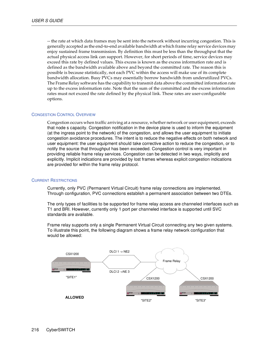
Frame Relay Accesses
Configuring a Frame Relay Access
Configuring a PVC
Frame Relay General Configuration Elements
Frame Relay PVC Configuration Elements
LMI
LMI Format
Dlci Value
PVC Name
Frame Relay Access Background Information
Local Management Interface Overview
Allowed
Not Allowed
Configuring Advanced Bridging
Bridge Dial OUT
Under ISDN, select Dial Out Phone Number
Bridge Mode of Operation
Spanning Tree Protocol
Bridge Mode of Operation Background Information
Configuring Bridge Filters Using Cfgedit
Bridge Filters
Protocol Definition Commands
Source MAC Filter Commands
Destination MAC Filter Commands
Protocol Filter Commands
Packet Data Filter Commands
Bridge Filter Configuration Elements
Lsap in HEX
Bridge Filters Background Information
Filter Type Maximum Number of Each
Filter Destination MAC
Protocol Definitions
Unrestricted Mode Bridge Filters
Source Discard Connect Destination Protocol Packet
USER’S Guide
Filter Action Distribution Result List
Packet matching this filter will not be forwarded
On any LAN port. The packet will be sent to remote
Sites connected over the WAN according to
Restricted Mode Bridge Filters
Restricted Mode Forwarding Action
Workgroup Remote Access Switch
Filter Distribution Result Action List
Packet matching this filter will only be forward
Ed on the LAN ports. The packet will not be sent to
Any remote sites connected over the WAN
Configuring a Destination MAC Address Filter
Preliminaries
Discard Connect
Configuring the Known Connect List
Known Connect List
Known Connect List Configuration Elements
Known Connect List Background Information
Configuring Advanced IP Routing
Static ARP Table Entries
Configuring Static ARP Table Entries Using Cfgedit
Static ARP Table Entries Configuration Elements
Static ARP Table Entries
Select Static ARP Table Entries from the IP menu
Isolated Mode
Static Route Lookup VIA Radius
Static Route VIA Radius Configuration Elements
Configuring AN IP Address Pool Using Cfgedit
IP Address Pool Configuration Elements
IP Address Pool
Initiating the IP Filter Configuration Using Cfgedit
IP Filters
IP Address Pool Background Information
Configuring Packet Types Using Cfgedit
Mask
TCP UDP Icpm
Specify a control value any, established, or not established
Select Icmp Type
Configuring Forwarding Filters
Select Add a Forwarding Filter
Configuring Connection Filters
Configuring Exception Filter
Applying Filters
Select IP Interfaces
Select Apply Global Forwarding Filter
Select Device Level Databases Select On-node Device Entries
IP Filters Configuration Elements
TCP and UDP Ports
NEQ
Range
IP Filters Background Information
Packet Types
Forwarding Filters
Connection Filters
Exception Filters
Application to Network Interfaces
Common Portion
Limitations
Example of AN IP Filter Configuration
FTP WWW Sfvra
Forward
Configuring a Dhcp Relay Agent Using Cfgedit
Dhcp Relay Agent
Dhcp Configuration Elements
Dhcp Background Information
Bridge to Bridge Environment
Router to Bridge Environment
IP Router to IP Router with Relay Agents on both
USER’S Guide
Remote Bridge to IP Router w/Relay Agent
= WAN Rlan
Configuring the Dhcp Proxy Client
Dhcp Proxy Client
Select Dhcp Proxy Client
Dhcp Proxy Client ENABLE/DISABLE Flag
Sample Configuration IP Router with Dhcp Proxy Client
Configuration for IP Router Chloe
Configuring IPX
Configuring IPX Information
ENABLING/DISABLING IPX Using Cfgedit
IPX Option Configuration Element
IPX Routing Option
Configuring the IPX Internal Network Number Using Cfgedit
IPX Internal Network Number Configuration Element
IPX Internal Network Number
IPX Option Background Information
Configuring IPX Network Interfaces Using Cfgedit
IPX Network Interfaces
IPX Network Number Background Information
LAN WAN
Displays the current IPX network interface data
IPX Network Interface Configuration Elements
SAP IPX Network Interface Configuration Elements
IPX Network Interface Background Information
Configuring IPX Routing Protocols Using Cfgedit
IPX Routing Protocol Configuration Elements
IPX Routing Protocols
IPX Routing Protocol Background Information
SAP
Special Considerations Remote LAN Interface
Configuring IPX Static Routes Using Cfgedit
IPX Static Routes
IPX Static Routes Configuration Elements
IPX Static Routes Background Information
IPX Netware Static Services
Configuring IPX Netware Static Services Using Cfgedit
IPX Netware Static Services Configuration Elements
IPX Netware Static Services Background Information
Configuring IPX Spoofing Using Cfgedit
IPX Spoofing
IPX Spoofing Configuration Elements
IPX Spoofing Background Information
Watchdog Protocol
Configuring IPX Type 20 Packet Handling Using Cfgedit
IPX Type 20 Packet Handling
IPX Isolated Mode
IPX Type 20 Packet Handling Configuration Elements
Configuring IPX Isolated Mode Using Cfgedit
IPX Isolated Mode Configuration Elements
IPX Isolated Mode Background Information
Displaying WAN Peer List
Configuring Triggered RIP/SAP Global Timers Using Cfgedit
Configuring IPX Devices
IPX-SPECIFIC Information for Devices
Triggered RIP/SAP Background Information
IPX-Specific Information for Devices
SPX Watchdog Spoofing Menu
Enable Bridging and disable Make calls for bridge data
IPX Configuration Elements for Devices
IPX Background Information for Devices
Configuring Snmp
Configuring Snmp
Configuring Snmp
Snmp Configuration Elements
Snmp Background Information
WAN
Workgroup Remote Access Switch
USER’S Guide
Configuring Appletalk Routing
Enabling Appletalk Routing Using Cfgedit
Appletalk Routing Option
Appletalk Routing Option Configuration Element
Configuring Appletalk Ports Using Cfgedit
Appletalk Ports
Appletalk Routing Background Information
Appletalk Ports Configuration Elements
Appletalk Ports Background Information
Overview
Configuration
Configuring Appletalk Static Routes Using Cfgedit
Appletalk Static Routes
Considerations
Appletalk Routing Static Routes Configuration Elements
Configuring Appletalk Capacities Using Cfgedit
Appletalk Capacities Configuration Elements
Appletalk Capacities
Appletalk Isolated Mode
Configuring the Appletalk Isolated Mode Using Cfgedit
Appletalk Isolated Mode Configuration Elements
Appletalk Capacities Background Information
Configuring Call Control
Configuring the Throughput Monitor Using Cfgedit
Throughput Monitor
Throughput Monitor Configuration Elements
Throughput Monitor Background Information
Condition Trigger Number Window Size Utilization
90%
Overload Condition Monitoring
Idle Condition Monitoring
Configuring the Call Interval Parameters Using Cfgedit
Call Interval Configuration Elements
Call Interval Parameters
Call Interval Background Information
Configuring Monthly Call Charge Using Cfgedit
Monthly Call Charge Configuration Elements
Monthly Call Charge
Monthly Call Charge Background Information
Configuring Call Restrictions Using Cfgedit
Call Restriction Configuration Elements
Call Restrictions
Call Restrictions
Call Restrictions Background Information
Configuring Bandwidth Reservation
Bandwidth Reservation
= CentralSite
Bandwidth Reservation Configuration Elements
Select Bandwidth Reservation
Configuring Semipermanent Connections Using Cfgedit
Semipermanent Connections
Bandwidth Reservation Background Information
Semiperm
Semipermanent Connections Configuration Elements
Call Device Commands
Semipermanent Connections Background Information
Call Restrictions
Throughput Monitor
Configuring VRA Manager for Call Control Using Cfgedit
VRA Manager AS a Call Control Manager
Background Information
LIMITATIONS/CONSIDERATIONS
Configuring Other Advanced Options
PPP Configuration
Configuring PPP
PPP Configuration Elements
PPP Background Information
PPP Reference Documents
Default Line Protocol
Configuring Default Line Protocol Using Cfgedit
Default Line Protocol Configuration Elements
Default Line Protocol Background Information
Configuring LOG Options Using Cfgedit
LOG Options Configuration Elements
LOG Options
UDP Port
LOG Options Background Information
CDR LOG Report Overview
Call Detail Recording Events
Event Report Contents
Connect Event Report Contents
Disconnect Event Report Contents
Reject Event Report Contents
System Up Event Report Contents
Verify Event Report Contents
Configuring Compression Options Using Cfgedit
Compression Options Configuration Elements
Compression Options
Compression Options Background Information
Compression and CCP
Configuring Tftp
Tftp
Tftp Configuration Elements
Tftp Background Information
Configuring File Attributes
File Attributes Configuration Elements
File Attributes
File Attributes Background Information
Users Report Files StatFiles CfgFiles Other Files
File category File types included in the category
RPRTLOG.1
STATLOG.1
Troubleshooting
System Verification
System Verification
Verifying Hardware Resources are Operational
Verifying WAN Lines are Available for USE
Verifying LAN Connection is Operational
Verifying Bridge is Initialized
Verifying IP Router is Initialized
Verifying a Dedicated Connection
Verifying a Frame Relay Connection
Verifying AN X.25 Connection
Verifying Remote Device Connectivity
Verifying MULTI-LEVEL Security
Ping 100.0.0.2 return
Verifying IP Host Mode is Operational
Verifying IP Host Mode is Operational
Verifying IP Host is Initialized
Verifying IP Routing Over Interfaces
Verifying IP Routing Over a LAN Interface
Verifying IP Routing Over a WAN Interface
100.0.0.1 100.0.0.0 Host B 192.100.1.3 Host a 100.0.0.2
Verifying IP Routing Over a WAN Direct Host Interface
Verifying IP Routing Over a WAN Remote LAN Interface
Verifying IP Routing Over a WAN Unnumbered Interface
Verifying IP Filters
Verifying IP RIP
Ip filter trace discard return
Verifying IP RIP is Initialized
Verifying IP RIP Output Processing on a LAN Interface
Verifying IP RIP Input Processing on a LAN Interface
Verifying IP RIP Output Processing on a WAN Interface
CSX1200 Router Dedicated Connection 100.1.1.1 192.1.1.1
Verifying IPX Router is Initialized
Verifying IPX Routing is Operational
Verifying IPX Routing Over a LAN Connection
Verifying AN IPX Remote LAN Connection
Xxxx
Verifying the Appletalk Routing Feature
Verifying IPX Routing Over a WAN Connection
Verifying Triggered RIP/SAP
Verifying Appletalk Routing is Initialized
Verifying Appletalk Routing is Operational
Verifying Appletalk Routing Operation Over a WAN Connection
Verifying Snmp is Operational
Verifying the Dial OUT Feature
Verifying Call Detail Recording
Verifying Compression is Operational
Verifying Reserved Bandwidth is Operational
Verifying PPP Link Failure Detection is Operational
Verifying Dhcp Relay Agent
Verifying Dhcp Relay Agent Initialization
Verifying the Relay Agent is Enabled
Verifying the Relay Agent is Operational
Verifying Dhcp Proxy Client
Verifying Dhcp Proxy Client Initialization
Verifying the Proxy Client is Enabled
Verifying the Proxy Client is Operational
UDP Ports
Verifying a Semipermanent Connection
Verifying Proxy ARP is Operational
Verifying Proxy ARP is Operational
Problem Diagnosis
General Procedures
Problem
LAN Adapter
Bridge Initialization
IP Routing Initialization
WAN Line Availability
Out Svc 1 slot #, port #
Dedicated Connections
Frame Relay Connections
Connections
Remote Device Connectivity
Set-up
Disabled
MULTI-LEVEL Security
LAN Attachment
IP Host Mode
IP Host Mode Operation Over the LAN Connection
IP Host Initialization
IP Host Mode Operation Over the WAN Connection
IP Routing Over Interface Connections
IP Routing Over the LAN Interface Connection
IP Routing Over a WAN Interface Connection
IP Routing Over a WAN Direct Host Interface Connection
IP Routing Over a WAN Rlan Interface Connection
IP Routing Over a WAN Unnumbered Interface Connection
If you are still experiencing problems
IP RIP Initialization
IP RIP Output Processing on a LAN Interface
IP RIP Input Processing on a LAN Interface
IP RIP Output Processing on a WAN Interface
IP RIP Input Processing on a WAN Interface
IPX Routing
IPX Routing Initialization
IPX Routing Over the LAN Connection
IPX Routing Over the Remote LAN Connection
IPX Routing Over the WAN Connection
IPX Routing and Service Tables
Appletalk Routing
Triggered RIP/SAP Start UP
Triggered RIP/SAP Operation
Appletalk Routing Initialization
Appletalk Routing Operational Over the LAN Connection
USER’S Guide
Appletalk Routing Operational Over the WAN Connection
Snmp
CyberSWITCH does not generate Snmp Trap PDUs
Set Up
Dial OUT
Call Detail Recording
Compression
Successful Negotiation
Peer Protocol-Rejects CCP
CyberSWITCH does not have Compression Enabled
Relay Agent Initialization
Enabling the Relay Agent
Relay Agent Operation
Proxy Client Initialization
Enabling the Proxy Client
Proxy Client Operation
Proxy ARP Operation
Proxy ARP Operation
LED Indicators
Local Area Network LED Indicators
PRI LED Indicators
Lanview Leds CSX1200-E11-MOD
Receive LEDs
OFF
Service Indicator
Service Indicator Remains LIT
Service Indicator Blinks
OUT SVC LAN Xmit Error
Alarm Leds PRI only
Alarm LEDs PRI Only
System Messages
Informational Messages
Boot Messages
Initialization Messages
Normal Operation Messages
Status Messages
Error Messages
System Message Summary
Spanning Tree Messages
Port LAN Adapter, operating in remote mode only
Port LAN Adapter, operating in local and remote mode
Call has exceeded the configured maximum duration
Adapter #’x’ failed to respond from bootstrap
Attempting to load FileName for Upgrade
Attempt to initialize unconfigured DM card in slot slot #
Auth ACE Could not create service file
Auth ACE Could not write service file
Auth ACE Encryption configured for DES not supported
Auth ACE Error receiving server log message acknowledgment
Auth ACE Login rejected user user name
Auth ACE Node verification received Client initialized
Auth Radius Login rejected device device name
Auth Radius IP Host rejected IP Host id IP host Id
Auth Radius IP Resolve rejected IP Address IP address
Auth Radius PAP rejected device device name
Auth Tacacs Login rejected user user name
Auth Warning code 0001 Timeout
Auth Warning code 0004 No authentication node available
Auth Warning code 0007 Authentication mode mismatch
Booting System Software
Bootstrap came alive on DM card in slot slot #
Bootstrap came alive on WAN card in slot slot #
Bad auth result in smgrauthaanotify for device device name
Call Restrictions have been disabled by user command
Call Restrictions have been enabled by user command
Calculating CRC’s
Calling Line ID Failure, Duplicate ID calling line Id
Call Restriction statistics reset for new day
Call Restriction statistics reset for new month
Call Restrictions will allow calls to be made this hour
Call Restrictions will allow calls to be made
Workgroup Remote Access Switch
Cause cause code received for Dlci dlci index
Cause Code Event
CCP Internal Decompression Failure
CCP Option Negotiation Failure, Non-Convergence detected
Chap Authentication Failure remote device not responding
Channel in use in Hostcallrequest
Configured adapter # ’x’ type does not exist
Couldn’t find speech service slot #, port #
Current monthly charges reset for new month
CNTR-TMRTimed out waiting for TMR number interrupt
Dedicated connection down slot #, port #
DHCP-P Failed to close UDP port x, erc = y
DHCP-P Failed to open UDP port for first Dhcp client
DHCP-P Failed to open UDP port x, erc = y
DHCP-P Proxy Client disabled
DHCP-P Proxy Client enabled
DHCP-R Relay Agent disabled
DHCP-P Proxy Client initialization failed
DHCP-R Relay Agent enabled
DHCP-R Relay Agent initialization failed
DHCP-R UDP port 67 closed
DHCP-R UDP port 67 opened
DM card in slot slot # signals it is operational
DM card type configured in slot slot # does not exist
DM card in slot slot # will not come out of reset
DM upgrade started. Board=board #, Modem=modem #
DM upgrade success. Board=board #, Modem=modem #
Downloading Bootstrap to DM card in slot slot #
Edrv transmit error error code
DSL test failed to establish Layer 1, port=port #
Error closing file ’s’
Error downloading bootstrap program to adapter #’x’
Error downloading operational software to adapter ’x’
Error during channel initialization Access access index
Error mapping WAN adapter #’x’ into Host memory map
Error parsing old WAN Direct Host interface bad format
Error opening file \system\ethernt2.bin
Error programming adapter #’x’ hardware
Error reading sdconf.rec file
Error requesting slot activation
Error sending message to Call Control
Facility not subscribed Slot=slot # Port=port #
Failed to obtain Terminal info in smgrprocterminalauthsess
Failure during read of file ’s’
Failure during Static RAM test on adapter # ’x’
Failure to allocate enough memory for Xilinx load file
USER’S Guide
File Access Err
Formatting Flash Memory
Frietf detected PPP protocol from NAME, shutting down PVC
Frame Relay event queue full
Installing File Set into Flash Memory
Interrupt fault on WAN Adapter in Slot slot #
FrUtl No registered device for Dlci dlci index
Initial TDM Clock Master slot#, line#
Invalid Cllm received on Access access index
Invalid Password password given
IP Error from ESP datagram discarded
IP x.x.x.x not added to the pool Unknown error y
IP Default Route not added, invalid next hop IP address #
IP Invalid configuration for Network Interface dd
Ipap ResMem returned invalid device maximum value
IP Cannot get system memory for
IP Invalid Peer IP Address IP address, WAN IP Stream Closed
IP IP host is initialized successfully
IP IP router is initialized successfully
IP Network initialized successfully on ddd.ddd.ddd.ddd
Ipcp IP Address Pool Out of IP addresses
Ipcp Option Negotiation Failure, Non-Convergence detected
Ipcp Remote device does not negotiate IP address
IP Host Call Dropped XID was not received from remote
IP Host Security Rejection Invalid Security ID Id string
IP RIP All network interfaces used
IP RIP Buffers allocated
IP RIP Initialization failed, unable to allocate buffers
IP RIP Unable to open RIP/UDP port
IP RIP Unable to register WAN Connection notification
IPX Invalid Ipxwc passed
IPX Network initialized successfully on
IPX SAP Space available in service table
IPX SAP Unable to add service, service table full
Ipxwan IPX Internal Network Number must be configured
IPX RIP Shutdown complete
LAN Adapter Command Timeout
LAN Adapter configuration conflict
LAN Adapter Fatal Error Reported
LAN Adapter HW upgrade may be required
LAN Adapter Reset
LAN Adapter Response Timeout
LAN Adapter System resource error
LAN Init Error
LAN Xmit Error
LMI alarm on Access access index
LMI alarm reset Access access index
LAN Port port # detected shorted LAN media
Manage Mode updates have been successfully committed
Memory Access Timeout
Manual intervention required please replace LAN card
Manual restart initiated on DM board in slot slot #
Mismatch of configured and installed DM card in slot slot #
Modem modem # of DM card in slot slot # is unusable
Modem revision on modem modem # of slot slot # failed
Negotiation Failure with Semipermanent device
Network sent Cause Spid not supported slot #, port #
Network sent Status with state = 0, tear down call
No Active Calls Active Sites
No Active List entry available in INM
Out of LAN Adapter transmit command descriptors
Not enough memory for Security module
Offnode server lookup of Dial Out User failed
Outgoing calls barred Slot=slot # Port=port #
Auto For over 5 minutes Report problem to Phone company
PAP Identification timeout on remote device
PAP Invalid password for name given by remote device
Out Svc # slot # , port #
PAP Remote device rejected System Information error message
PAP Unknown name name given by remote device
Post number, Hdlc #number External Loopback Test Failed
Post number, Hdlc #number Internal Loopback Test Failed
RBS LIFAddTimer failure
RBSoutSMchannel # Timeout waiting for Wink
PVC for Dlci dlci index not Active
PVC not allocated for dlci index
Reattempting to Install File Set into Flash Memory
Rebooting
Replace Lithium Battery Contact your Representative
Reserved signal
Security Rejection Invalid Password password given
Retrying download of DM card in slot slot# in x seconds
Rx Channel Inactivity Detected
Security Rejection Caller did not negotiate security
Security Rejection No Password given by caller
Security Rejection Timeout on Startup Complete
Semipermanent. Device x disconnected by admin
Security Rejection No Protocol List supplied
Semipermanent. Device x reconnected by admin
Signal for unknown CallCmd task task Id
Slot #, port # Cfg Error
Snmp Authentication failure, unknown community name
SSB Post 27 i960timer82c54FAILURE
SSB Can’t read RTC prior to i960 POSTs
SSB Couldn’t read RTC during i960 POSTs
SSB i960 Post number not equal to i386’s
SSB Post 28 i960lan82596sx Failure
SSB Post 29 i960lan82503 Failure
SSB Post 30 i960permodmem1 Failure
SSB Post 31 i960permodmem2 Failure
Successfully Loaded Release X.Y Issue Z
Switch could not recognize phone number nnnnnnn
System Clock Fault on Wan Adapter in Slot slot #
STP a Blan Topology Change has been detected
Tftp Local error #2 Feature not initialized
Tftp Local error #3 Server not initialized
Tftp Local error #4 UDP rejected packet filename
Tftp Local error #5 UDP open failed
Tftp Local error #13 Received unexpected opcode filename
Tftp Local error #14 Bad file name
Tftp Local error #15 Bad mode string
Tftp Local error #18 Unable to open file filename
Tftp Remote error # 0 Text from Remote Host
Tftp Remote error # 1 Text from Remote Host
Tftp Remote error # 2 Text from Remote Host
Tftp Remote error # 3 Text from Remote Host
Compression subsystem is not enabled
Timeout detected on connection establishment
Timeout detected on receiving caller’s number
Timeout on Startup Complete
Type mismatch of configured & installed adapter # ’x’
Unable to Decrypt Datagram
Unable to get Digital Modem resource to place call
Unable to open \config\devdb.nei file
Unable to open Modem Upgrade file
Unable to restore original ISRs for Interrupt interrupt #
Unable to Identify a remote device
Unexpected error during transmission of LMI frame
Unmatched Login Task
Updating CyberSWITCH from FileName
WAN card in slot slot # signals it is operational
Watchdog timeout detected on DM board in slot slot #
Watchdog timeout detected on WAN board ’x’
X25 facilities error, facilities not allowed in PVC
X25 facilities error, bad facility length
X25 facilities error, reverse charging not accepted
X25 facilities error, fast select not available
X25 facilities error, fast select not accepted
X25 facilities error, throughput negotiation not allowed
Zone allocation failed, maximum capacity already configured
X25 facilities warning, NUI not available
Zone allocation failed, increase zone table capacity
Trace Messages
Call Trace Messages
Location Causes
Call Trace Message Summary
Configure ack slot #
Inband treatment has been applied
-BRD CFG ACK Slot=slot #
Init data link slot #, port #, ces
Out configure port #
Interworking unspecified cause
Off-hook warning tone on
Origination call address is non-ISDN
Received unknown signal value
Out init data link slot #, port # , ces
Recall dial tone on
Received unknown progress value
IP Filters Trace Messages
PPP Packet Trace Messages
Configure Request
Configure ACK
Configure NAK
Configure Reject
Trace Messages
Echo Reply
Discard Request
Trace Message Summary
X25 Data LCN logical channel number, number of bytes bytes
X25 DCE RR LCN logical channel number, number of bytes bytes
System is sending a call request to the network
Lapb Trace Messages
Lapb Trace Message Summary
Lapb Sabme
Lapb UA
Out Lapb Disc
Out Lapb DM
System Maintenance
Remote Management
Remote Management
Installation and Configuration
SITE.2
Usage Instructions
Telnet
Earlier Releases
Usage Instructions
Tftp Client PC
Users Report Files Statistics Files Config files Other Files
Remote Installation with USER2
USER’S Guide
System Commands
Accessing Administration Services
Setting the IP Address
Boot Device Commands
Accessing Dynamic Management
Viewing Operational Information
List relnote.txt
Viewing Operational Information
Status
Second column is the potential number of connections
Viewing Throughput Information
100
Throughput Monitor Contents
Saving Operational Information
CONFIGURATION-RELATED Commands
Clearing Operational Information
Restarting the Cyberswitch
Setting the Date and Time
File Utility Commands
Terminating Administration Sessions
Login-Id
Appletalk Routing Commands
Type
State
Default zone
Network range
Flags
LAN port
Distance
Zones valid
Zone
Bridge Commands
Call Control Commands
Device name must be re-entered
Calling phone number at data rate, device PPP
Call Detail Recording Commands
Call Restriction Commands
Compression Information Commands
Dhcp Commands
Frame Relay Commands
Clears all statistics associated with the fr stat command
IP Routing Commands
Disables the trace
Valid Icmp Echo Reply was received from host ddd.ddd.ddd.ddd
Mask used for the destination
Age of the route in seconds
IPX Routing Commands
Ipx ping host ipx address
Isdn Usage Commands
Isdn usage
LAN Commands
LOG Commands
Packet Capture Commands
All packets will be captured
Following is an example pkt display screen
Banyan Vines Packet Detail Screen Bridged Packet
Radius Commands
Radius ipres
Snmp Commands
TCP Commands
Telnet Commands
Used to close the current Telnet connection to a target host
Possible send parameters are defined as follows
Terminal Commands
Tftp Commands
Tftp GET
Trace Commands
Tftp Session
UDP Commands
User Level Security Commands
WAN Commands
Commands
Clears the statistics for the default VC
System Statistics
Connectivity Statistics
Call Restriction Statistics
Call Statistics
Throughput Monitoring Statistics
Appletalk Statistics
Appletalk Protocol Statistics
Number of AppleTalk Echo requests received
Count of AppleTalk Echo replies received
Number of NBP LookUp Requests received
Appletalk Port Statistics
Bridge Statistics
Call Detail Recording Statistics
Compression Statistics
Compression Related Statistics
Decompression Related Statistics
Dhcp Statistics
Dhcp Relay Agent statistics and Dhcp Proxy Agent statistics
Common Dhcp Statistics
Dhcp Relay Agent Statistics
Dhcp Proxy Client Statistics
Access Related Statistics
Frame Relay Statistics
Not currently supported
PVC Related Statistics
LAN Statistics
IP Statistics
IP Group Statistics
Icmp Group Statistics
Number of Icmp Destination Unreachable messages received
IPX Statistics
IPX General Statistics
Number of IPX packets received with incorrect checksums
IPX RIP Statistics
IPX Triggered RIP Statistics
IPX Route Statistics
IPX Service Statistics
IPX Triggered SAP Statistics
RIP Statistics
RIP Global Statistics
RIP Interface Statistics
Snmp Statistics
SnmpInReadOnlys
TCP Statistics
Tftp Statistics
Statistics for Server or Remote Initiated Tftp Activity
Statistics for Local or Client Initiated Tftp Activity
Statistics for ALL Tftp Activity
UDP Statistics
WAN Frietf Statistics
Layer 1 PRI Error Statistics
Layer 1 General Statistics
WAN Statistics
Statistics
Virtual Circuit VC Related Statistics
Local DTE X.121 address
Routine Maintenance
INSTALLING/UPGRADING System Software
Executing Configuration Changes
Making Changes Using Cfgedit
Configuration Backup and Restore
Making Changes Using Manage Mode
Obtaining System Custom Information
Appendices
System Worksheets
System Worksheets
Network Topology
System Details
Resources
Lines
Accesses
Authentication Information Frame Relay Information
Device Information
Bridging and Routing Information
IP Routing
IPX Routing
Appletalk Routing
AppleTalk Routing/Port Information
Main Menu
IPX
Snmp PPP
FR DBU
Physical Resources Menu
DES, Feal
Hdlc PPP FR DBU
BPS
Options Menu
WAN Rlan
Dhcp
Snmp
FR DBU
Security Menu
Radius Tacacs ACE
Isdn
SVC, PVC
PPP STAC-L25
VRA Manager TCP port
Reporting Problems
Getting Assistance
Contacting Cabletron Systems
To Customer Service From
Phone FAX Cabletron Systems System Problem Report
Number of Pages Including this
Administrative Console Commands Table
Command Use
Displays help screen
Displays or clears current AppleTalk port statistics
Command Use Cdr stats clear
Verifies call detail recording servers are configured
Clears administration screen
Clears current call detail recording statistics
Dlci
Generates a triggered RIP/SAP update request to
Local log file only displays the call detail recording log
Log cdr erase
Local log file only erases the call detail recording log
Changes password for current access level
Displays system errors and system messages
Displays the current Tftp statistics
Displays current software version and hardware resource
Revision information
Access or the specified access
Specified X.25 access
Manage Mode Commands Table
Ipxspoof Allows you to configure system level spoofing data
Adds/changes/deletes an IPX address from the IPX
Address pool
Manage Mode Commands Table
USER’S Guide
Cause Codes Table
USER’S Guide
Cause Codes Table
USER’S Guide
Workgroup Remote Access Switch
USER’S Guide
Dec Value Hex Value Cause
Unknown
Index
Br stat
CDR
Cdr 534 cfg
Cmp 535 commands
Date
Del 524 destfilt
Device 162
Device add
Ip addrpool 535, 537 IP filters 241
Ipcp
Isdn
Lan 545 LAN adapter
Lan test 355 Lanview LEDs 420 Lapb
Led status 518 line
NTT INS
STAC-LZS
Restart 523 restore
Sentry
Spid
Srcfilt
Term 554 term set 357 terminal mode
Udp
Wr 52, 521 ws 52
X25