Configuration
PVC Connection
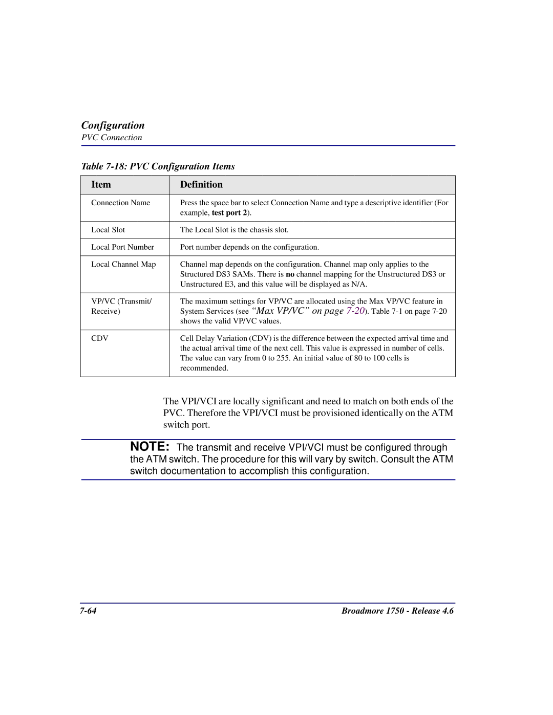
Table 7-18: PVC Configuration Items
Item | Definition |
|
|
Connection Name | Press the space bar to select Connection Name and type a descriptive identifier (For |
| example, test port 2). |
|
|
Local Slot | The Local Slot is the chassis slot. |
|
|
Local Port Number | Port number depends on the configuration. |
|
|
Local Channel Map | Channel map depends on the configuration. Channel map only applies to the |
| Structured DS3 SAMs. There is no channel mapping for the Unstructured DS3 or |
| Unstructured E3, and this value will be displayed as N/A. |
|
|
VP/VC (Transmit/ | The maximum settings for VP/VC are allocated using the Max VP/VC feature in |
Receive) | System Services (see “Max VP/VC” on page |
| shows the valid VP/VC values. |
|
|
CDV | Cell Delay Variation (CDV) is the difference between the expected arrival time and |
| the actual arrival time of the next cell. This value is expressed in number of cells. |
| The value can vary from 0 to 255. An initial value of 80 to 100 cells is |
| recommended. |
|
|
The VPI/VCI are locally significant and need to match on both ends of the PVC. Therefore the VPI/VCI must be provisioned identically on the ATM switch port.
NOTE: The transmit and receive VPI/VCI must be configured through the ATM switch. The procedure for this will vary by switch. Consult the ATM switch documentation to accomplish this configuration.
Broadmore 1750 - Release 4.6 |